Electronic switch for drop-free candle

a drop-free, electronic switch technology, applied in the direction of capillary burners, lighting and heating apparatuses, combustion types, etc., can solve the problems of difficult control of the flame of the candle, present certain difficulties in mass production, and the prior art's control device of the candle light control device is comparatively complicated

Inactive Publication Date: 2005-11-01
YU SHUNG LUN
View PDF9 Cites 26 Cited by
  • Summary
  • Abstract
  • Description
  • Claims
  • Application Information

AI Technical Summary

Benefits of technology

[0006]The primary purpose of the present invention is to provide an electronic switch that prevents the burning candle from creating any drop, thus to ensure the complete combustion of the candle but also eliminate drop resulted from diverged wick or flame for improved safety.
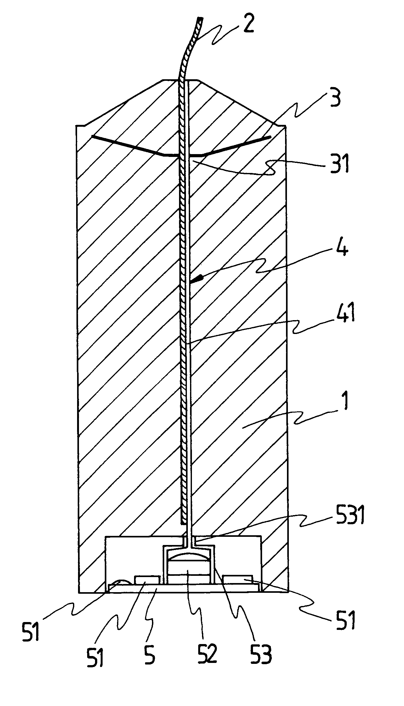
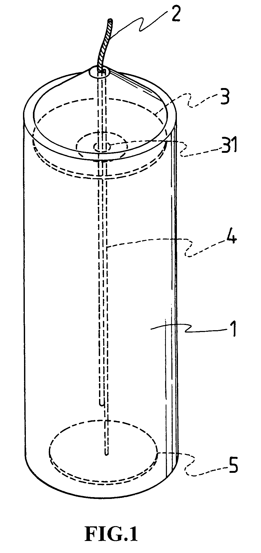
[0007]To achieve the purpose, the present invention is essentially comprised of a candle, a wick, a metal disk, a conductor and a circuit board. Wherein, the metal disk is provided inside the candle, and the conductor provided along the wick relates to a optical fiber or magnet twisted pair cable; so that once the candle is ignited, the conductor controls the circuit board provided at the bottom of the candle to realize the function of an electronic switch while the metal disk prevents the drop of the fatty substance of the candle.
[0010]To the present invention, the candle is melted not by the heat from the flame, instead, by the heated metal plate. Therefore, the melting is achieved at constant speed to eliminate the gap while the metal plate also stops the fatty substance from escaping to ensure complete combustion of the candle without creating drop.

Problems solved by technology

However, the candlelight control device of the prior art is comparatively complicate to present certain difficulties in mass production.
However, it is difficult to control the flame of the candle and the burning wick may not keep straight all the time.
The diverged flam often winds up that the certain part of the candle to the peripheral of the wick melts faster and even creates a gap.
The fatty substance of the candle flows out to become drops that affect the appearance of the candle and quickly consume the candle.

Method used


Image

  • Electronic switch for drop-free candle
  • Electronic switch for drop-free candle
  • Electronic switch for drop-free candle

Examples


Embodiment Construction

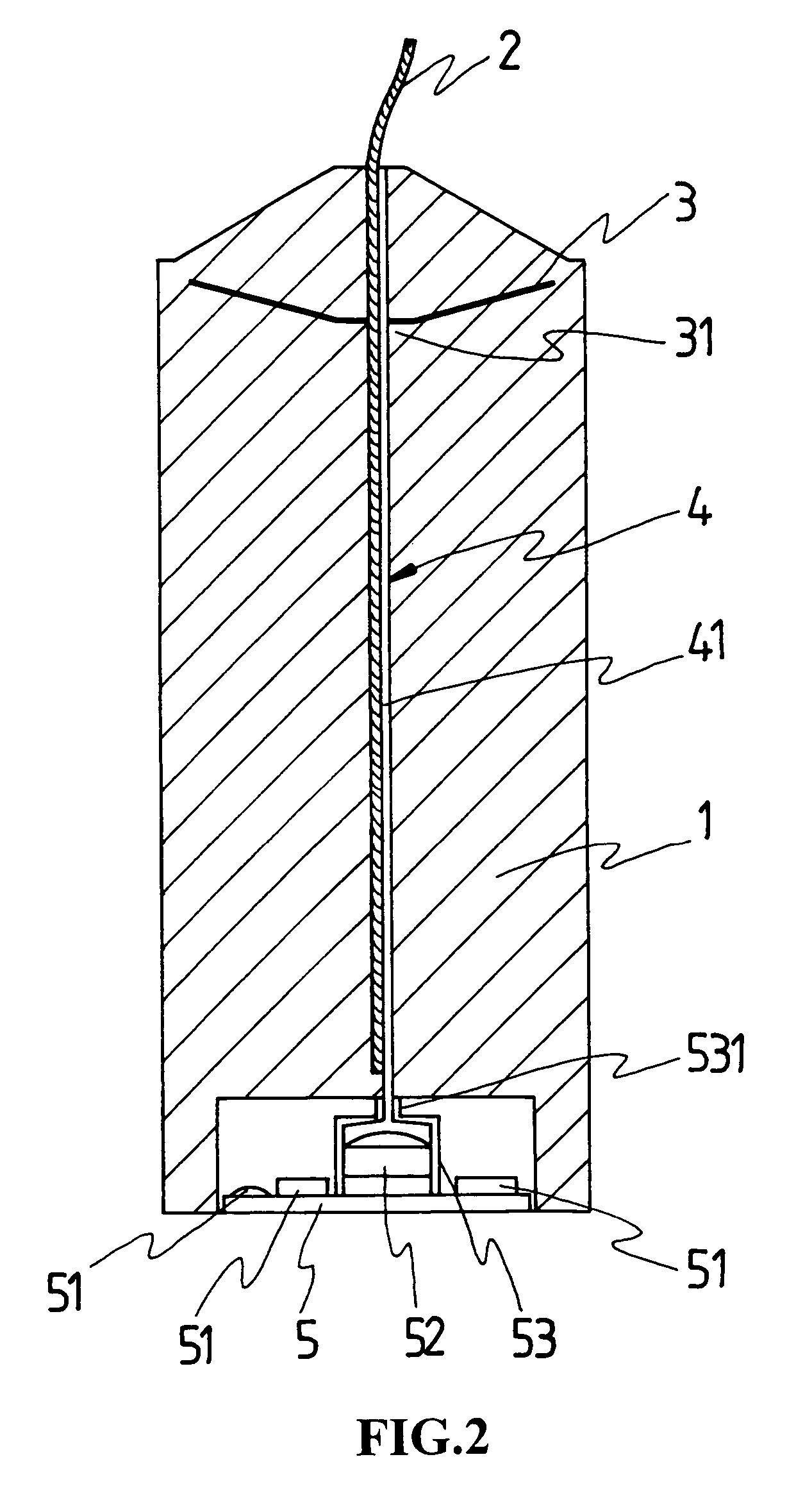
[0016]Referring to FIG. 1, a drop-free electronic switch of the present invention is essentially comprised of a candle 1, a wick 2, a metal disk 3, a conductor 4, and a circuit board 5. The present invention controls the electronic device by means of the burning candle to ensure complete combustion of the candle without creating drops due to diverged wick or flame for improved safety in use. Wherein, the wick 2 made of cotton is axially provided in the candle 1 for the wick 2 to stay burning on the top of the candle 1. A metal disk 3 made of aluminum foil and indicating a V shape is buried in the upper part of the candle 1. A circular opening 31 is provided at the center of the metal disk 3 to allow the wick 2 to penetrate through the metal disk 3. The circuit board 5 is provided at the bottom of the candle 1 and connected to a conductor 4 along the wick 2.

[0017]As illustrated in FIG. 2, the conductor 4 relates to an optical fiber 41. An electronic device 51 and a photosensitive dev...


PUM


Abstract

An electronic switch for a drop-free candle is comprised of a candle, a wick, a metal disk, a conductor and a circuit board; the metal disk being buried in the candle; the conductor being provided in the form of an optical fiber or a magnet twisted pair cable; the conductor being provided along the wick to control the operation of the circuit board provided at the bottom of the candle to realize the function of an electronic switch while preventing drops of the fatting substance of the candle.

Description

BACKGROUND OF THE INVENTION[0001](a) Field of the Invention[0002]The present invention is related to an electronic switch for a candle, and more particularly, to a conductor comprised of a optical fiber or a magnet twisted pair cable provided along a wick of the candle to control flaring, musical and other candle light variations while preventing drop of the fatty substance of the candle.[0003](b) Description of the Prior Art[0004]Whereas a conventional candle is no longer a strictly portable light, its application tends to try multiple-layer and multi-directional development particularly in the entertaining purpose. Electronic flaring candle and musical candle are now generally available in the market. Usually, the burning wick controls the flaring or musical function. As the candle must be ignited to flare or sound musical tones, an electronic switch to control the candlelight is introduced. The switch while controlling the inherited electronic device in the candle also controls o...

Claims


Application Information

Patent Timeline
Patent Type & Authority Patents(United States)
IPC IPC(8): F23D3/00F23D3/18
CPCF21S6/001F23D3/18
Inventor YU, SHUNG-LUN
Owner YU SHUNG LUN
Why Eureka
Try Eureka