Lighted switch sheet and lighted switch unit using the same

a technology of lighted switch and switch unit, which is applied in the direction of discharge tube/lamp details, discharge tube luminescnet screen, moving contact, etc., can solve the problems of high cost and increase in achieve the effect of reducing the number of components, simple structure and less cos

Inactive Publication Date: 2005-11-01
PANASONIC CORP
View PDF6 Cites 25 Cited by
  • Summary
  • Abstract
  • Description
  • Claims
  • Application Information

AI Technical Summary

Benefits of technology

[0014]The above structure has an advantage of providing the lighted switch sheet with capability of illuminating a plurality of push buttons above the movable contacts with only one EL element, thereby reducing the number of components, and making it simple in structure and less expensive.

Problems solved by technology

This results in an increase in number of components as well as a time required for assembly, which gives rise to a problem of high cost.

Method used


Image

  • Lighted switch sheet and lighted switch unit using the same
  • Lighted switch sheet and lighted switch unit using the same
  • Lighted switch sheet and lighted switch unit using the same

Examples


first exemplary embodiment

(First Exemplary Embodiment)

[0023]A lighted switch sheet of this invention is now described as a first exemplary embodiment.

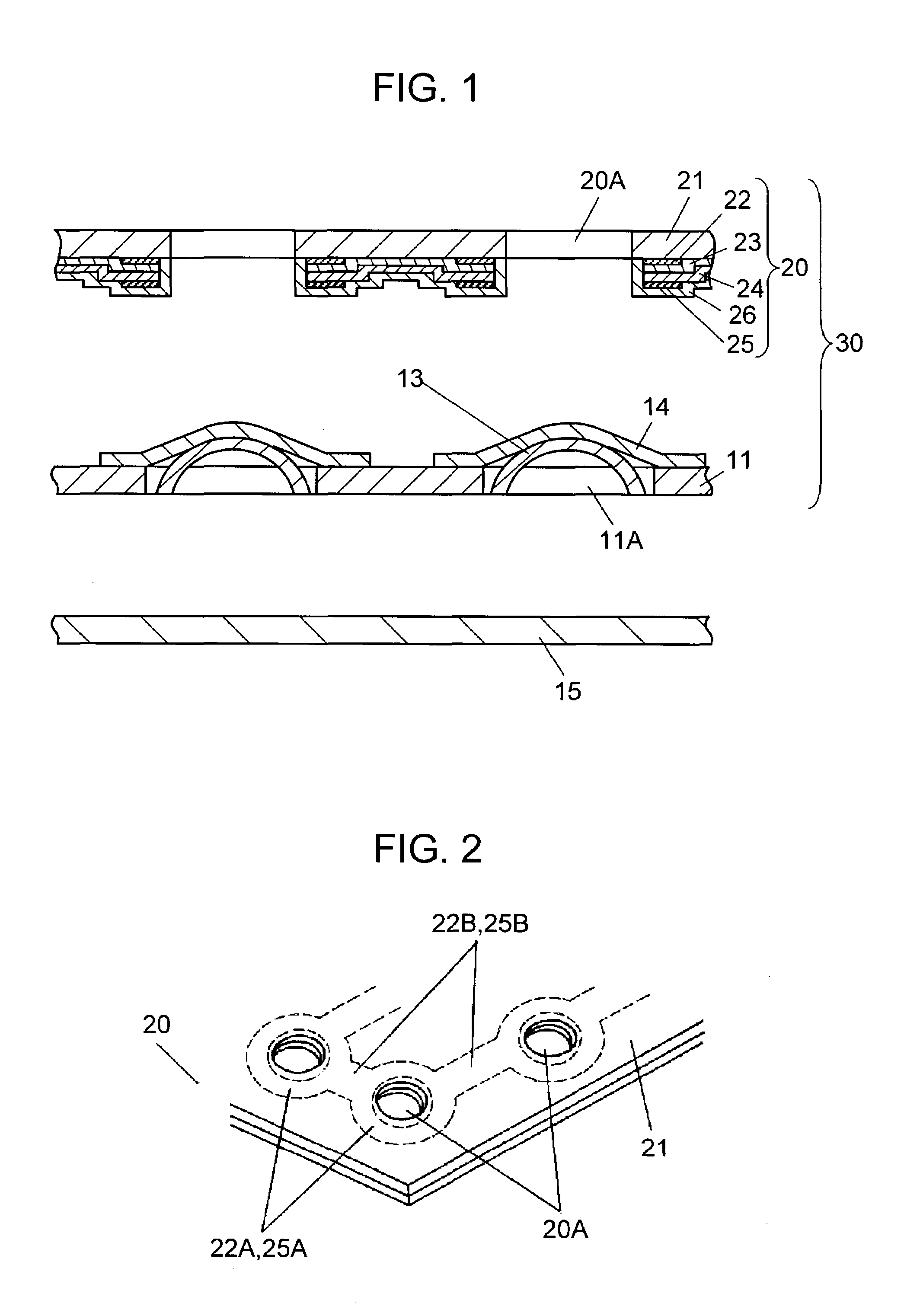
[0024]FIG. 1 and FIG. 2 illustrate the exemplary embodiment of this invention. Sheet 11 made of a plastic film such as polyethylene terephthalate, polyimide and the like material is provided with a plurality of fixing holes 11A formed therein as shown in FIG. 1.

[0025]Movable contacts 13 are generally in a hemispherical shape with their center convexed upward. They are disposed individually to the plurality of fixing holes 11A in sheet 11, and fixed to sheet 11 with tape 14 having adhesive (not show in the figure) coated on the underside surface. Movable contacts 13 are made of a thin metal plate having resiliency such as copper, copper alloy, and the like.

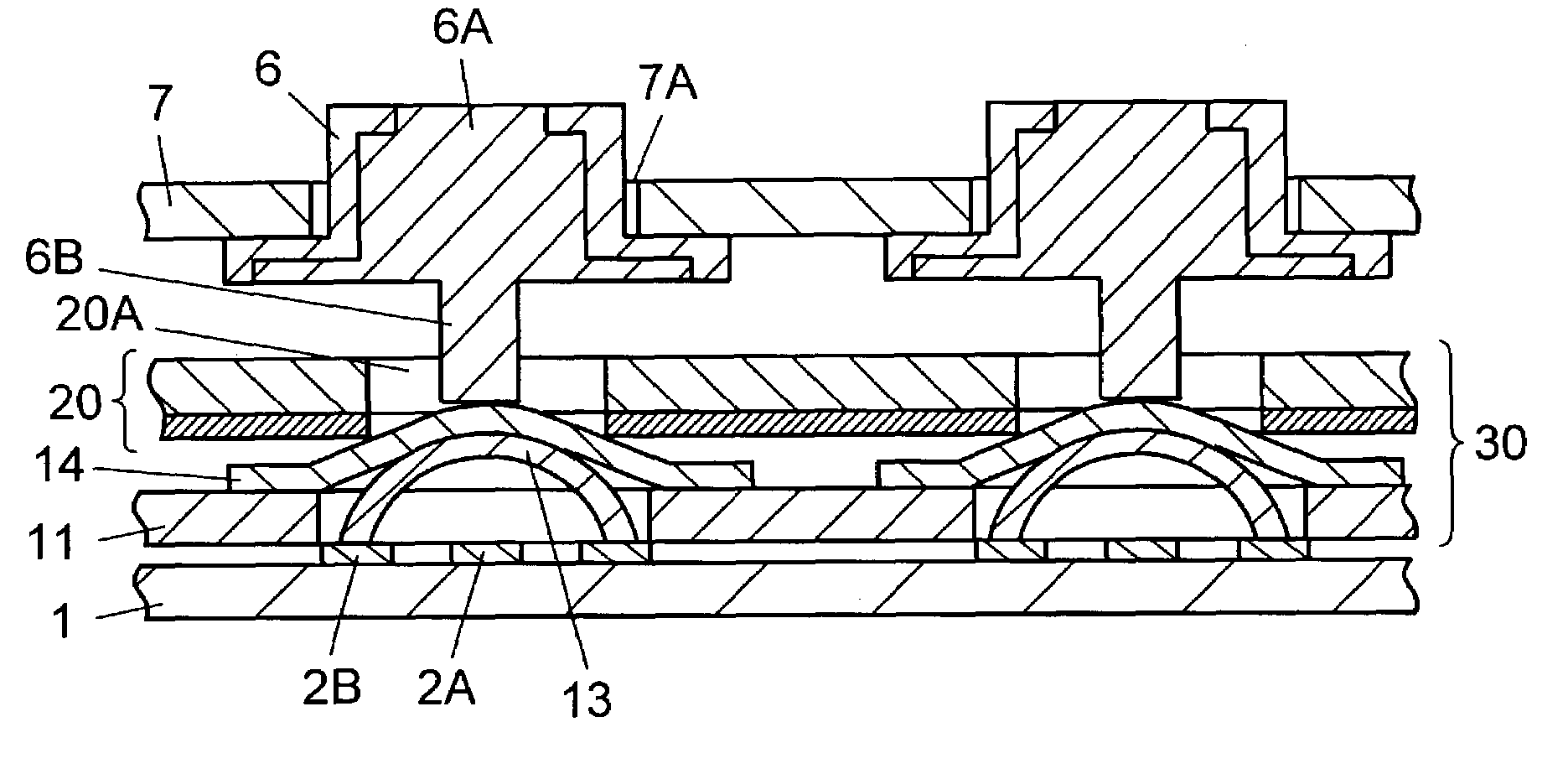
[0026]Further, EL element 20 is placed on the second surface of sheet 11. EL element 20 is provided with a plurality of through holes 20A formed in locations above their corresponding movable contacts 13, thro...

second exemplary embodiment

(Second Exemplary Embodiment)

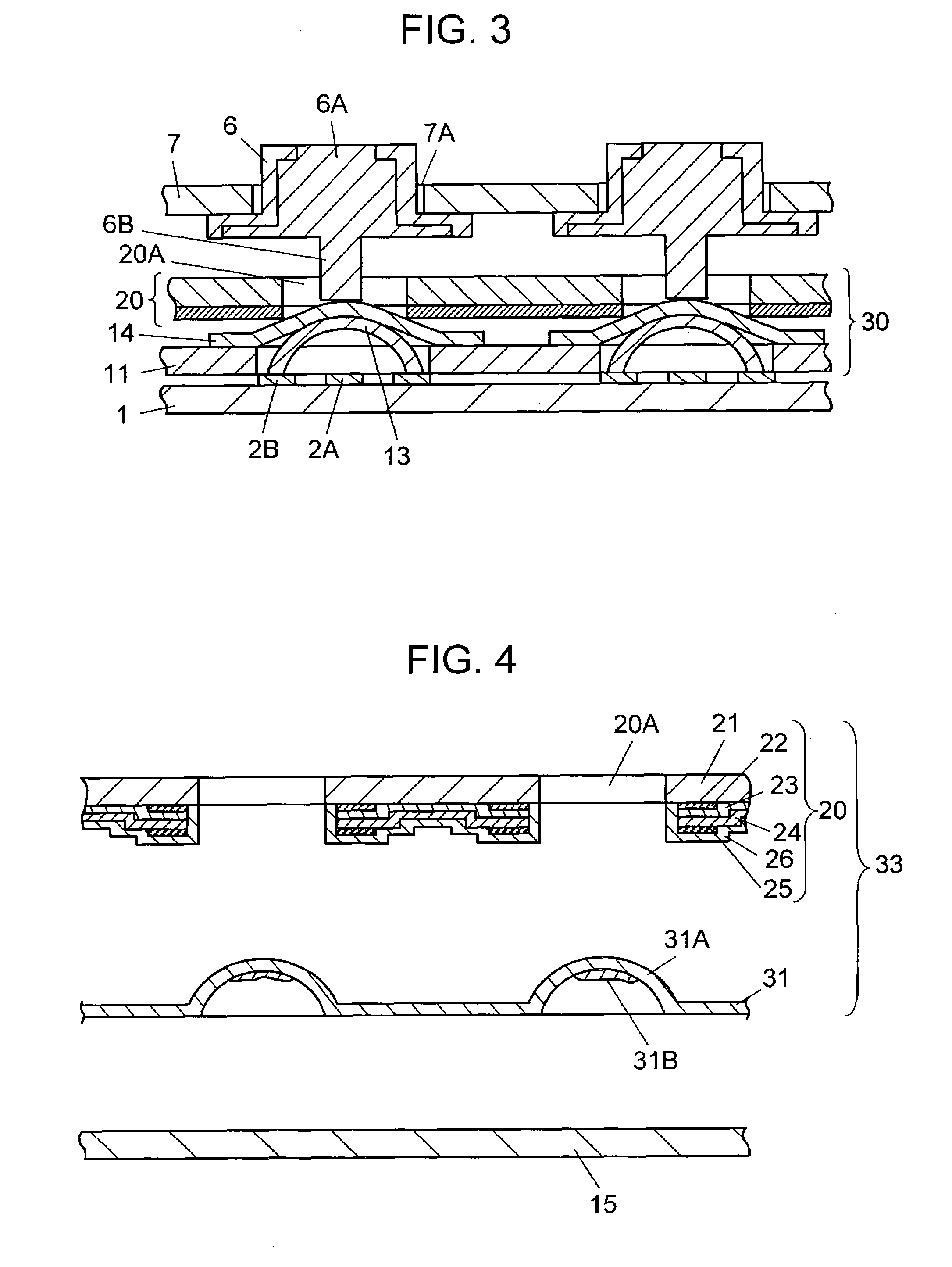
[0045]Another lighted switch sheet 33 of this invention is described with reference to FIG. 4 and FIG. 5. Like reference numerals are used to designate like structural components as those of the first exemplary embodiment.

[0046]This exemplary embodiment is similar to the first exemplary embodiment in respects that a plurality of through holes 20A are formed in EL element 20, optically transmitting electrode layer 22 and back electrode layer 25 are formed in a continuous pattern around the outer peripheries of the plurality of through holes 20A, and these layers are covered with insulating layer 26, as shown in FIG. 4.

[0047]Sheet 31 is then affixed on an underside surface of EL element 20. Unlike the structure of the first exemplary embodiment, lighted switch sheet 33 is not provided with movable contacts 13 of resilient thin metal plate, but sheet 31 has a plurality of unitary formed convex portions 31A protruding upward into generally a hemispherical sh...


PUM


Abstract

A lighted switch sheet of the invention has a structure, which comprises a sheet having a plurality of movable contacts of a hemispherical shape disposed in a plurality of fixing holes, and an EL element affixed on an upper surface of the sheet. The EL element has an optically transmitting substrate provided with an optically transmitting electrode layer, light-emitting layer and back electrode layer formed in an overlapping manner on an underside surface thereof, and through holes of a size slightly smaller than an outer diameter of the movable contacts formed above their respective movable contacts. The invention provides for the lighted switch sheet with a small number of structural components and a simple structure at low cost.

Description

TECHNICAL FIELD[0001]The present invention relates to lighted switch sheets used for lighting control panels of a variety of electronic apparatuses such as cellular phones, personal computers, and the like. The invention also relates to lighted switch units using the same.BACKGROUND OF THE INVENTION[0002]There is a rapid progress in performance and diversification in recent years of a variety of electronic apparatuses such as cellular phones and personal computers, and the like. In pace with the progress, a strong demand exists for means to make control panels such as push buttons legible and operable even in a dark environment. There is thus an increase in number of apparatuses that illuminate control panels using lighted switch units and lighted switch sheets provided with various kinds of light-emitting devices. A lighted switch unit of such kinds of the prior art will be described hereinafter with reference to FIG. 6.[0003]FIG. 6 is a cross sectional view of a lighted switch uni...

Claims


Application Information

Patent Timeline
Patent Type & Authority Patents(United States)
IPC IPC(8): H01H13/70H05B33/02H05B33/00H01H13/14H01H13/02H01H13/702
CPCH01H13/7006H05B33/00H05B33/02H01H2205/026H01H2219/018
Inventor HANAHARA, TETSUROISHIKAWA, TAKAYUKIABE, YOSHIHARU
Owner PANASONIC CORP
Why Eureka
Try Eureka