Combined stator core for an electric rotary machine

a stator core and electric rotary machine technology, applied in the direction of dynamo-electric machines, electrical apparatus, magnetic circuit shape/form/construction, etc., can solve the problems of reducing the mechanical connection strength of the teeth block, and reducing the number of coupling pairs.

Inactive Publication Date: 2005-11-01
DENSO CORP
View PDF23 Cites 10 Cited by
  • Summary
  • Abstract
  • Description
  • Claims
  • Application Information

AI Technical Summary

Benefits of technology

[0031]Preferably, the first annular plates, the second annular plates, the first teeth, and the second teeth are constituted by a plurality of electromagnetic steel plates being multilayered. With this arrangement, it becomes possible to reduce the number of coupling pairs of the recessed portion and the protruding portion located next to each other in the lamination direction. Thus, the coupling work can be simplified.
[0032]Preferably, the teeth fixing pin is a plurality of pins spaced in the radial direction by a predetermined distance and located at the same position in the circumferential direction. With this arrangement, it becomes possible to enhance the mechanical connecting strength of the teeth block. The magnetic excitation force applied on a radial directional cross section of the teeth block can be reduced. The vibration of the teeth block caused by the reaction of the motor torque can be reduced, too. Furthermore, most of the magnetic flux flowing in the teeth block is directed to the radial direction. Thus, locating (or overlapping) the plurality of teeth fixing pins at the same position in the circumferential direction is effective in reducing the current induced in a short-circuit path formed by the plurality of teeth fixing pins and the electromagnetic steel plates.
[0033]Preferably, a first tooth or a second tooth is connected to other first tooth or other second tooth neighboring in the circumferential direction via an overhanging flange which extends from an inner end of the first tooth or the second tooth so as to close a slot. With this arrangement, the number of the first teeth or second teeth connectable in the circumferential direction can be increased under the condition that these teeth are inserted into the inner cylindrical portion of the yoke. Thus, the anti-vibration strength of the teeth block can be increased.
[0034]Preferably, the protruding portions and the recessed portions are constituted by a plurality of electromagnetic steel plates being multilayered. With this arrangement, each protruding portion becomes thick in the axial direction so that the bending durability in the axial direction can be enhanced. With this arrangement, when the protruding portion is inserted into a corresponding recessed portion, the protruding portion is prevented from being bent in the axial direction and being offset or deviated from a target position in the axial insertion. Especially, this arrangement brings remarkable effects in the case that numerous protruding portions are disposed at predetermined intervals in the circumferential direction. Namely, this arrangement prevents respective protruding portions from being dislocated in the axial direction. Thus, all of the protruding portions can be surely inserted into corresponding recessed portions. Regarding the electromagnetic steel plates constituting the yoke, it is possible to bond and integrate them at an appropriate timing prior to insertion of the teeth block into the yoke. Similarly, it is possible to bond and integrate the teeth at an appropriate timing prior to insertion of the teeth block into the yoke.
[0035]Preferably, the yoke includes a plurality of recessed portions being overlapped at predetermined intervals in the axial direction. The teeth block includes a plurality of protruding portions being overlapped at predetermined intervals in the axial direction and being respectively inserted into the recessed portions of the yoke. And, a ratio of a total width of the protruding portions in the axial direction to a total width of the recessed portions in the axial direction is in a range from 0.8 to 1.2. With this arrangement, it becomes possible to reduce the axial gap between the recessed portion and the protruding portion and accordingly reduce the magnetic resistance. Furthermore, it becomes possible to increase a facing area between the protruding portion and the recessed portion and accordingly reduce the magnetic resistance.
[0036]Preferably, the recessed portion and the protruding portion being inserted into the recessed portion are configured into rectangular shape when seen from the axial direction. A convex corner of the protruding portion and a concave corner of the recessed portion being fitted to each other are chamfered. And, a ratio Rx / Ry is in a range from 1.0 to 1.5, where Rx represents a curvature radius of the convex corner of the protruding portion and Ry represents a curvature radius of the concave corner of the recessed portion. With this arrangement, when the protruding portion is inserted into the recessed portion, the convex corner of the protruding portion smoothly guides the insertion of the protruding portion. Furthermore, this arrangement brings the effect of reducing an average clearance between the convex corner of the protruding portion and the concave corner of the recessed portion in the radial direction in the condition that the protruding portion is inserted into the recessed portion.

Problems solved by technology

However, as the yoke and teeth are constituted by electromagnetic steel plates being multilayered, the surfaces of the recessed portions and the protruding portions formed on the yoke and teeth remain uneven or undulated.
If required to reduce the gap formed between the recessed portions and the protruding portions when the yoke and teeth are engaged or fitted, constituting the yoke and teeth with the electromagnetic steel plates being multilayered will become difficult.
However, the radial coupling type combined stator core is inferior to the axial coupling type combined stator core in that the circumferential width of each recessed portion cannot be reduced so much at its opening end.
Thus, there is a problem that the teeth may be pulled out the yoke in the radial direction due to magnetic vibrations.
Not only the combined stator cores disclosed in the Japanese Patent Application Laid-open No. 61-124241(1986) and the Japanese Utility Model Laid-open No. 5-11754(1993) but also many of other conventional combined stator cores have a problem in that it is difficult to eliminate the gap (or clearance) between the teeth and yoke formed when they are faced with each other.
Accordingly, when electric power is supplied to a stator coil, the magnetic vibrations caused by the stator core induce chattering vibrations in the teeth and accordingly generate noises.
Furthermore, the magnetic resistance in the above-described gap is so large that the efficiency of the electric rotary machine decreases significantly.

Method used


Image

  • Combined stator core for an electric rotary machine
  • Combined stator core for an electric rotary machine
  • Combined stator core for an electric rotary machine

Examples


first embodiment

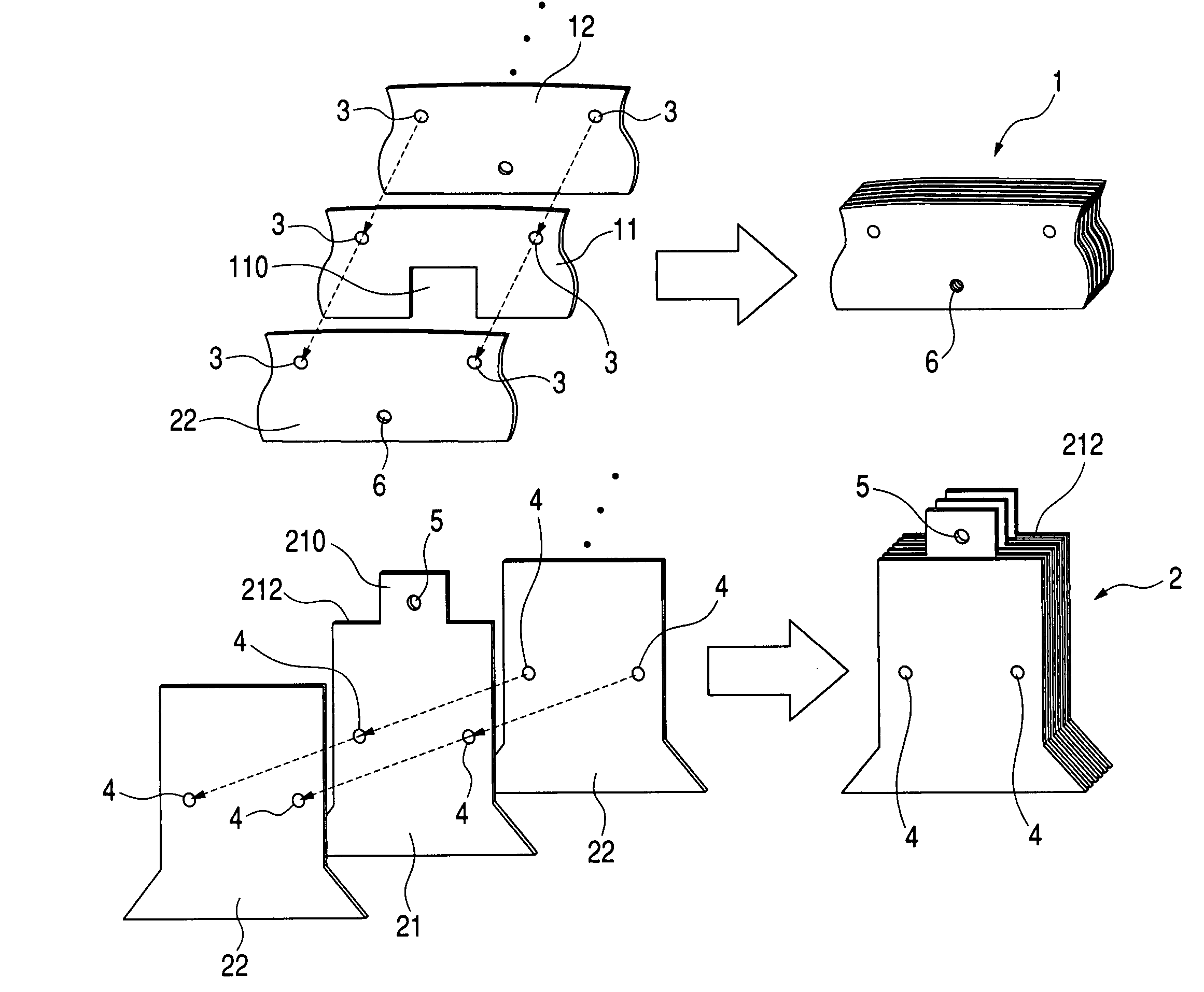
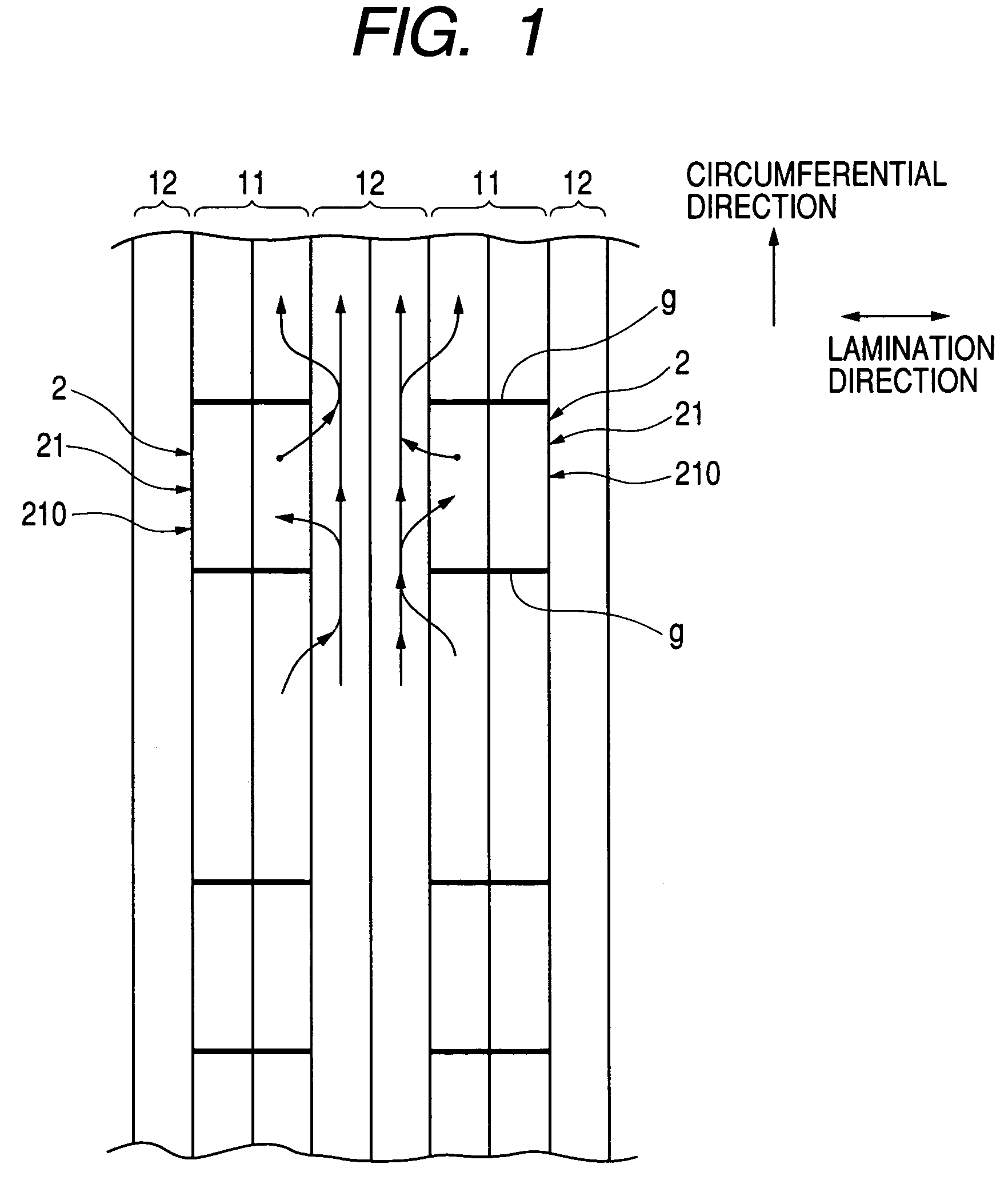
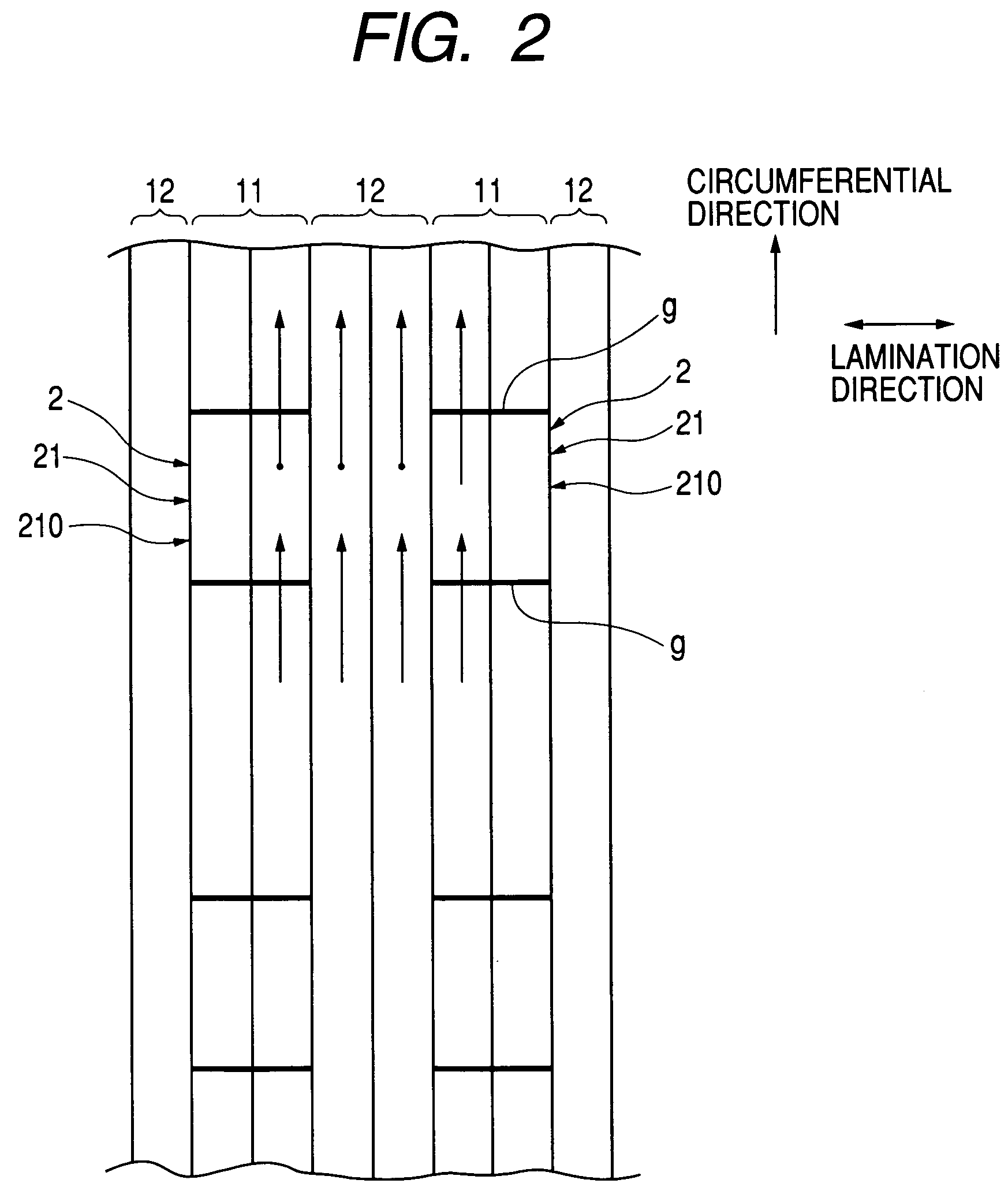
[0067]A combined stator core according to a first embodiment of the present invention will be explained hereinafter with reference to FIGS. 5 and 6. A combined stator core includes a cylindrical yoke 1 and a plurality of teeth block 2 coupled or fitted into an inner cylindrical surface of the yoke 1 at predetermined pitches in the circumferential direction. FIG. 5 is a partial perspective view showing a part of the yoke 1 and a single teeth block 2. FIG. 6 is a partial cross-sectional view showing the yoke 1 and the teeth block 2 shown in FIG. 5, taken along the axial direction (i.e., lamination direction).

[0068]The yoke 1 includes first annular plates 11 and second annular plates 12 which are alternately laminated so as to form a multilayered body. Each of the first annular plates 11 and the second annular plates 12 is made of a single disk-like electromagnetic steel plate. The teeth block 2 includes first teeth 21 and second teeth 22 which are alternately laminated so as to form a...

second embodiment

[0078]According to the above-described first embodiment, respective teeth blocks 2 are separated from each other. However, as shown in FIG. 13, it is possible to connect two or more same teeth (i.e., first teeth 21 or second teeth 22) with an overhanging flange 25 of the teeth block 2 protruding from the inner radial ends of the teeth block 2 in the circumferential direction so as to narrow the slot. It is preferable that, as shown in FIG. 14, the overhanging flange 25 has a narrowed portion 25′ in the center of the circumferential direction where the radial width of the flange 25 is narrowed to reduce the leakage of the magnetic flux. Furthermore, as shown in FIGS. 15 and 16, it is preferable to connect a pair of the first tooth 21 and the second tooth 22 or more. Furthermore, it is preferable as shown in FIGS. 17 and 18 that the combination of a single second tooth 22 and two (or more) consecutive first teeth 21 is used to constitute the teeth block 2. FIG. 18 is a view showing th...

third embodiment

[0079]FIG. 19 is a view showing another embodiment of the present invention. According to this embodiment, each of the recessed portion 110 and the protruding portion 210 has a circumferential width decreasing continuously toward the outer radial direction. This arrangement effectively prevents the protruding portion 210 from being obstructed by the sharp edges of the recessed portion 110 when the protruding portion 210 is first inserted into the recessed portion 110. It is also preferable that the second annular plate 12 has a small recessed portion and the first tooth 21 has a small protruding portion being coupled or fitted into the small recessed portion of the second annular plate 12.

Modified Embodiment

[0080]The first annular plates 11, the second annular plates 12, the first teeth 21, and the second teeth 22 are constituted by one or a plurality of electromagnetic steel plates.


PUM


Abstract

A yoke includes a plurality of recessed portions. A teeth block includes a plurality of protruding portions being coupled or fitted into the recessed portions of the yoke. The recessed portions and the protruding portions are disposed as a plurality of pairs in the lamination direction. The protruding portions and the yoke are fixed with a teeth fixing pin.

Description

BACKGROUND OF THE INVENTION[0001]This invention relates to a combination type stator core constituted by multilayered electromagnetic steel plates and employed in an electric rotary machine.[0002]The Japanese Patent Application Laid-open No. 61-124241(1986) or the Japanese Utility Model Laid-open No. 5-11754(1993) discloses a combined stator core including a plurality of separate electromagnetic steel plate members combined into a multilayered structure. The Japanese Patent Application Laid-open No. 61-124241(1986) discloses an axial coupling type combined stator core including a cylindrical yoke having numerous recessed portions (i.e., groove portions) arranged at predetermined pitches in the circumferential direction and opened toward one end in the radial direction and teeth having protruding portions engaged or fitted into the recessed portions of the yoke in the axial direction.[0003]The Japanese Utility Model Laid-open No. 5-11754(1993) discloses a radial coupling type combine...

Claims


Application Information

Patent Timeline
Patent Type & Authority Patents(United States)
IPC IPC(8): H02K1/14H02K1/18H02K15/02
CPCH02K1/148
Inventor YONEDA, SHIGENORISEGUCHI, MASAHIROINOMATA, NORIYASU
Owner DENSO CORP
Why Eureka
Try Eureka