Electric circuit system

a circuit system and circuit technology, applied in the field of electric circuit systems, can solve the problems of increasing power loss, inoperable safety-critical switch-off paths, etc., and achieve the effect of reducing rdson, being reliable and practical in use, and being more easily implemented

Inactive Publication Date: 2005-11-01
ROBERT BOSCH GMBH
View PDF10 Cites 1 Cited by
  • Summary
  • Abstract
  • Description
  • Claims
  • Application Information

AI Technical Summary

Benefits of technology

[0009]According to one exemplary embodiment of the circuit system of the present invention, the at least one IC is configured as a CMOS-IC which has a highside transistor and a lowside transistor as output driver, the highside transistor and the lowside transistor exhibiting different source-drain resistances in the switched-on state. Such components may be made available, and prove to be robust and reliable in practical use.
[0010]The drain-source resistors of the lowside transistors may be smaller than the drain-source resistors of the highside transistors. Due to this dimensioning, the L-level is adjustable as the dominant level, which corresponds to the switched-off, and thus generally less critical state of a function. The lowside transistors may be configured as N-channel MOSFETs, since they may be implemented more easily with lower RDSon than as P-channel MOSFETs.

Problems solved by technology

Typical difficulties within the framework of a FMEA analysis are, for example, that short circuits between adjacent PINs, (i.e. output PINs of output drivers) must not lead to a safety-critical switch-off path becoming inoperative.
In addition, the power loss rises, since in the case of an L-level, a current permanently flows through the pull-up resistor.

Method used


Image

  • Electric circuit system
  • Electric circuit system
  • Electric circuit system

Examples


Embodiment Construction

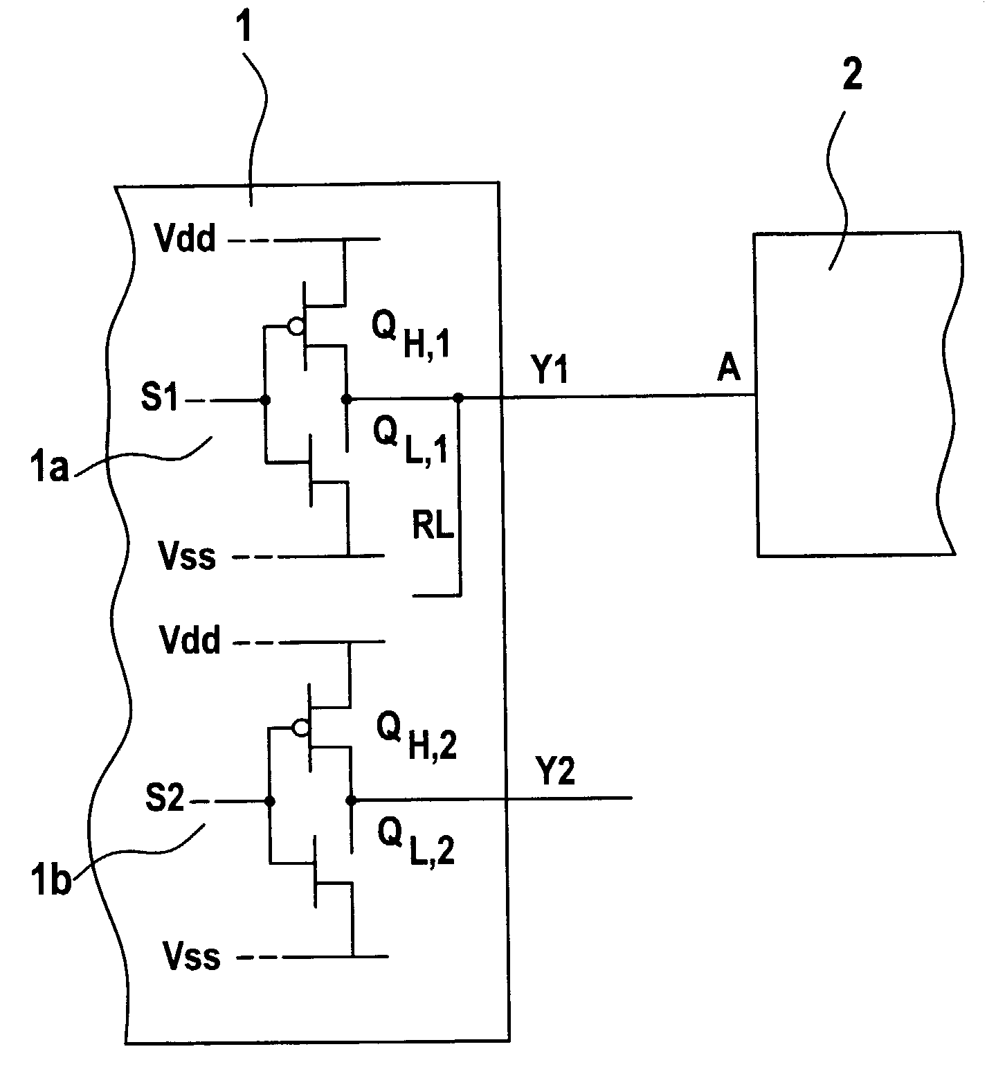
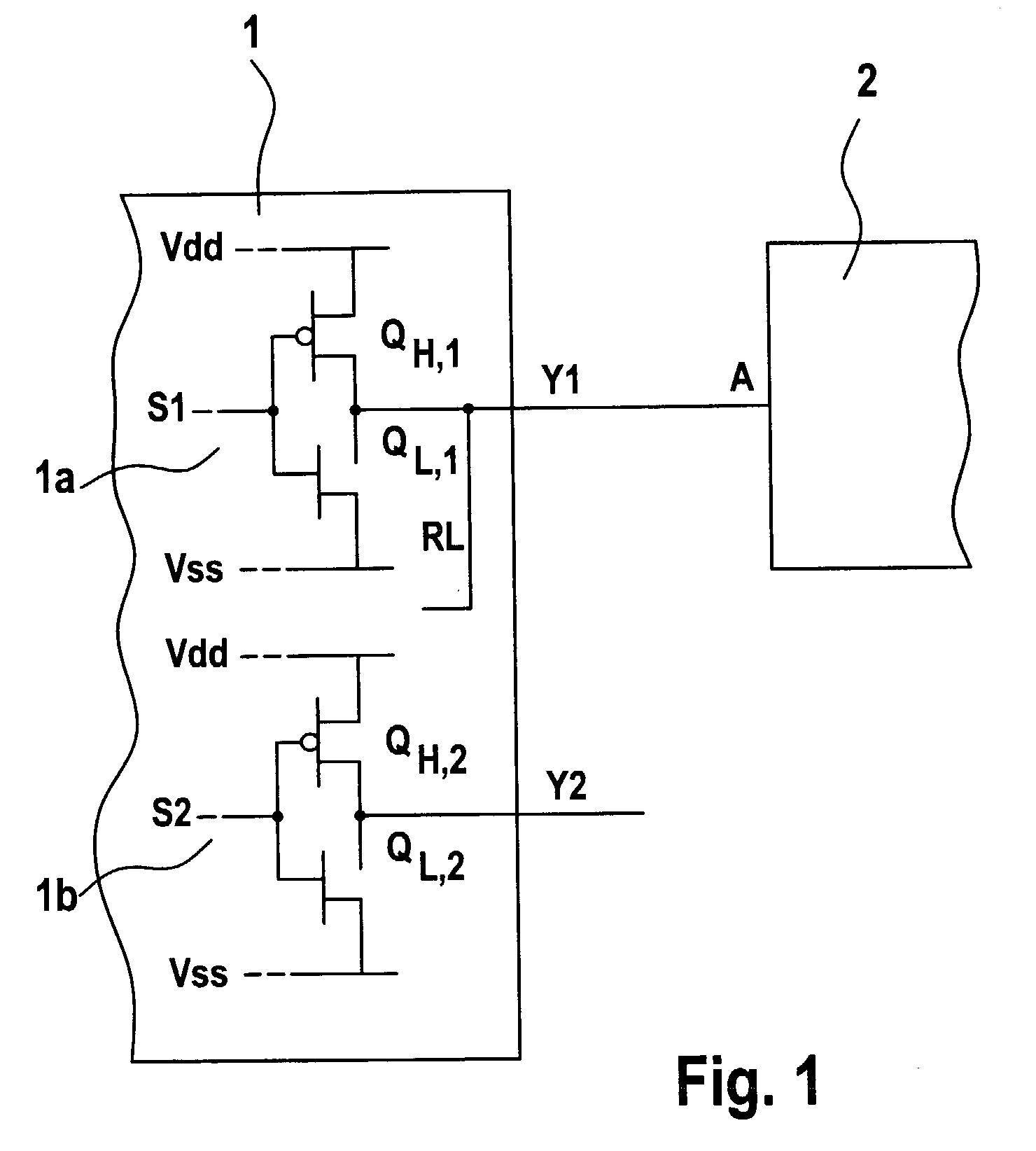
[0013]In FIG. 1, a first IC is designated by reference number 1, and a second IC is designated by reference number 2. First IC 1 has two output drivers 1a, 1b. Output drivers 1a, 1b are implemented using CMOS technology, and have in each case a highside transistor QH,1 and QH,2, respectively, and a lowside transistor QL,1 and QL,2, respectively.

[0014]The input signals of output drivers 1a, 1b are designated as S1 and S2, respectively; their output signals are denoted by Y1 and Y2, respectively. The output signal Y1 of the first output driver is transmitted as an input signal A to the second IC. A readback path RL is also provided, by which it must be ensured that a fault in the signal transmission from Y1 to A is detected. The supply-voltage levels to which the circuit system is connected are denoted by Vdd and Vss, respectively. For the sake of simplicity, in the following, voltage level Vdd is denoted as supply voltage, and voltage level Vss is denoted as ground. If a short circui...


PUM


Abstract

An electric circuit system for detecting a short circuit between output PINs of different ICs, particularly CMOS-ICs, which in each case have a first switching element, particularly a highside transistor and a second switching element, particularly a lowside transistor as output driver, the first switching element and the second switching element of the respective output drivers having different source-drain resistances in the switched-on state.

Description

FIELD OF THE INVENTION[0001]The present invention relates to an electric circuit system which is configured to detect a short circuit between pins of adjacent output drivers of a CMOS-IC.BACKGROUND INFORMATION[0002]German Published Patent Application No. 197 21 366 relates to an electric circuit system for checking a series connection, made of a switch and a load, having a first circuit which is connected to a connection point between the switch and the load and which is suitable for detecting a first state, the first state representing a short circuit of the connection point to the supply voltage. This circuit system provides a second circuit which is parallel-connected to the first circuit wherein the second circuit is connected to the connection point and is suitable for detecting a second or a third state, the second state representing a short circuit of the connection point to ground, and the third state representing an interruption of the connection point to the supply voltage...

Claims


Application Information

Patent Timeline
Patent Type & Authority Patents(United States)
IPC IPC(8): G01R31/28G01R31/02H01L21/822H01L27/04H03K19/00
CPCG01R31/2853G01R31/025G01R31/52
Inventor HAEUSER, THOMASHESSELBARTH, JOHANNES
Owner ROBERT BOSCH GMBH
Why Eureka
Try Eureka