
Surface acoustic wave filter with attenuation poles

Inactive Publication Date: 2005-11-01
LAPIS SEMICON CO LTD
View PDF8 Cites 0 Cited by
  • Summary
  • Abstract
  • Description
  • Claims
  • Application Information

AI Technical Summary

Benefits of technology

[0016]In view of the problems mentioned above, an object of the invention is to provide a high-performance SAW filter having lower insertion loss in a pass band and high attenuation in an attenuation band on the low frequency side of the pass band.

Problems solved by technology

The high performance SAW filter is being investigated with the use of traditional bonding wire, but satisfying characteristics are not obtained yet under present circumstances.
However, satisfying characteristics cannot be obtained yet.
However, required characteristics are not satisfied in this case as well.
However, the required characteristics are not satisfied.

Method used


Image

  • Surface acoustic wave filter with attenuation poles
  • Surface acoustic wave filter with attenuation poles
  • Surface acoustic wave filter with attenuation poles

Examples


first embodiment

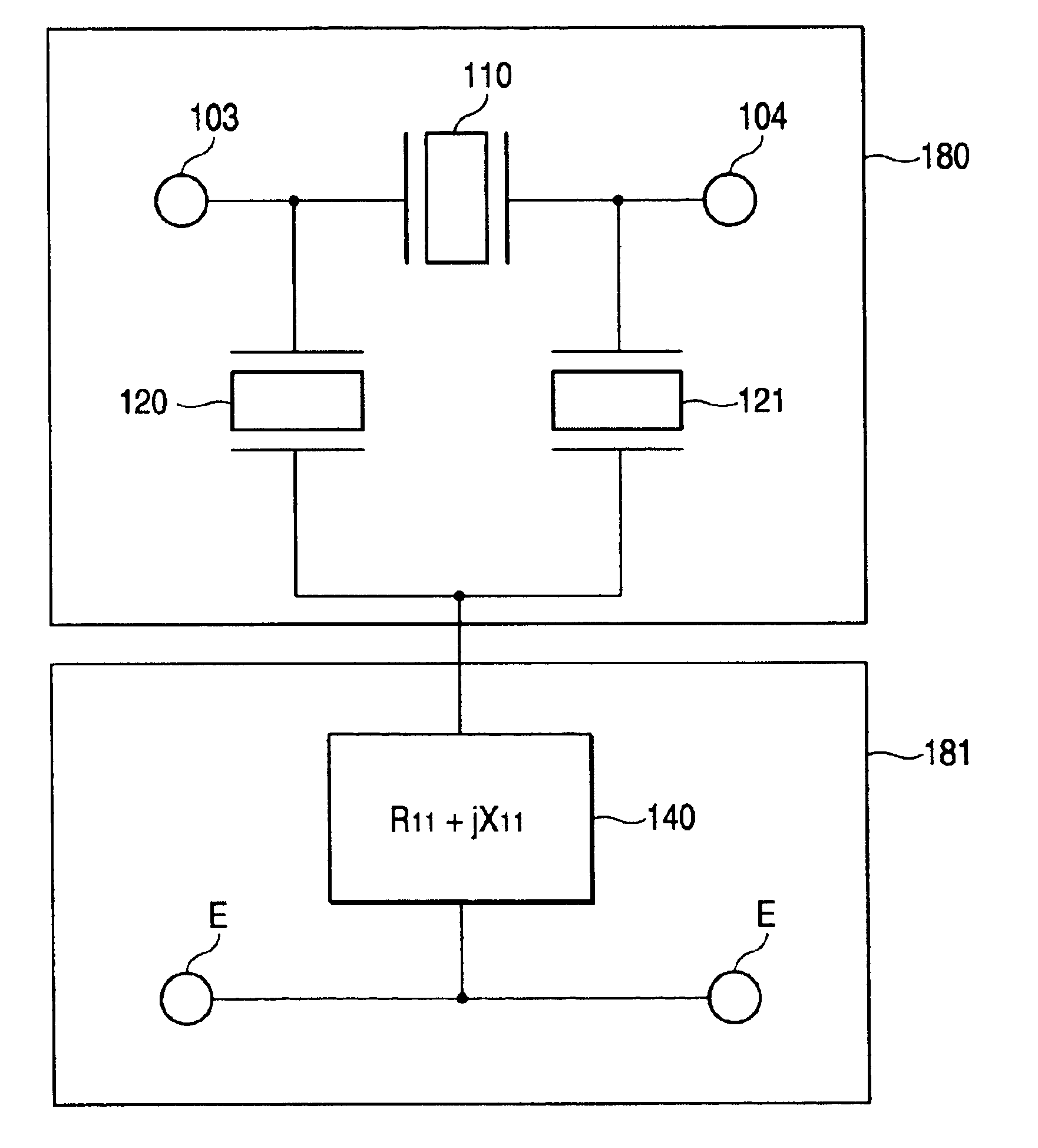
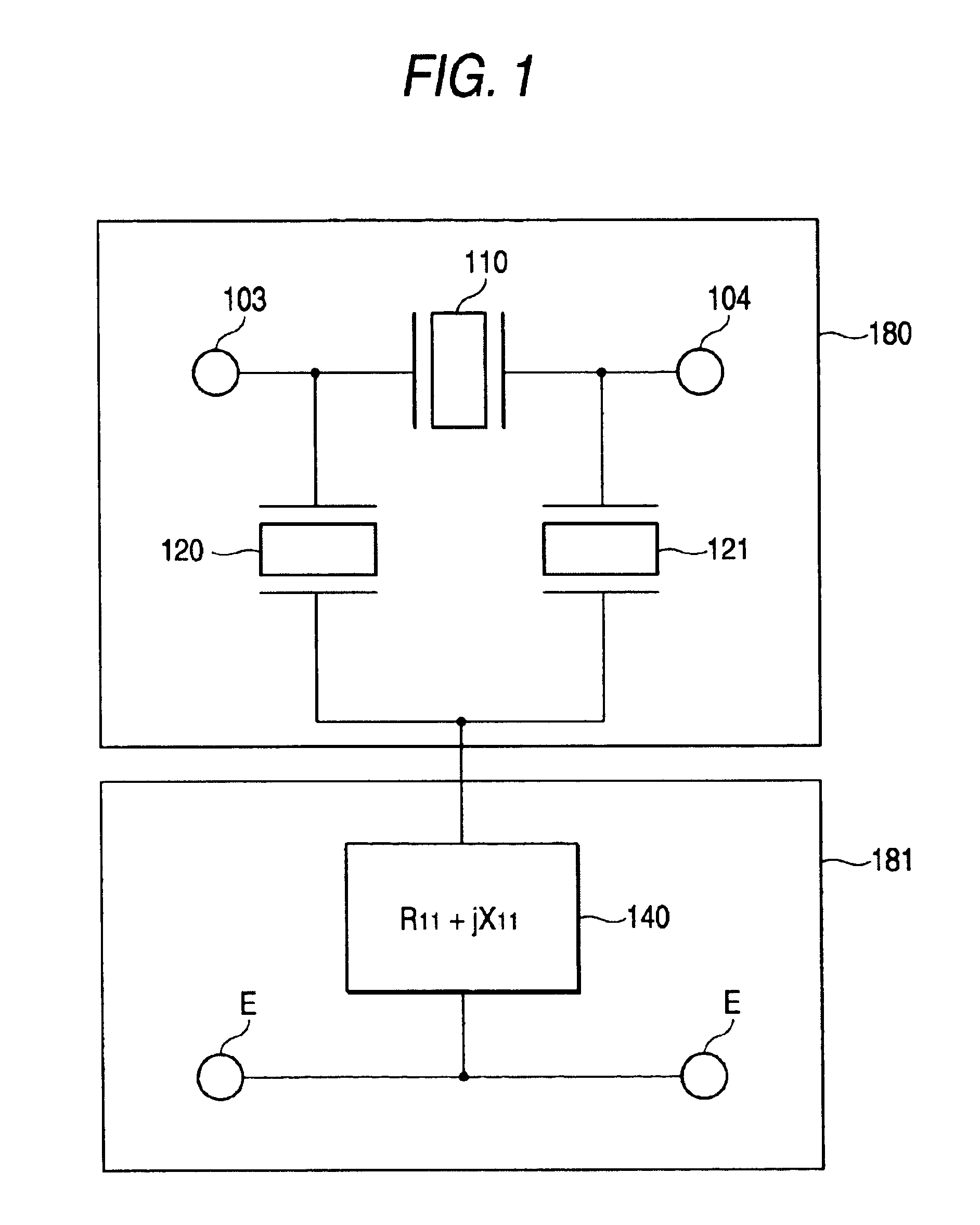
[0041]FIG. 1 is a diagram illustrating the circuit configuration of a first embodiment according to the invention.

[0042]The first embodiment is configured in which a two-port circuit for filtering 180 formed of a ladder type SAW filter of two-stage π type is serially connected to a two-port circuit 181 using an attenuation pole impedance Z11 140 serially connecting a resistance R11 to an inductance X11, as depicted by solid lines in FIG. 1.

[0043]More specifically, a series arm S1110 is serially connected between an input terminal 103 and an output terminal 104, and shunt arms 120 and 121 are connected in parallel to the both ends of the series arm 110 for forming the ladder type SAW filter of two-stage π type.

[0044]The two-port circuit for impedance 181 is formed of the attenuation pole impedance Z11 140. The impedance Z11 140 is configured as R11+jX11.

[0045]The invention is characterized in that the two-port circuit for impedance 181 is configured in which the pole frequency of the...

second embodiment

[0087]FIG. 5 is a schematic diagram illustrating a second embodiment according to the invention.

[0088]In the second embodiment, a two-port circuit for filtering 280 is configured as a ladder type SAW filter of the two-stage π type having the same circuit configuration as that of the first embodiment, and a two-port circuit for impedance 281 is configured as a π type circuit using three impedances. Each of three impedances Z21 241, Z22 242 and Z23 243 is configured of a resistance R and an inductance X.

[0089]More specifically, the two-port circuit for filtering 280 has one series arm 210 and two shunt arms 220 and 221.

[0090]The two-port circuit for impedance 281 is configured as a π type circuit with an attenuation pole impedance Z21 241 having R1+jX1, an attenuation pole impedance Z22 242 having R2+jX2 and an attenuation pole impedance Z23 243 having R3+jX3.

[0091]

TABLE 3Configurationseries armshunt armshunt armof resonators210220221Intersection607070length (μm)Logarithm808080

[0092] ...


PUM


Abstract

A high-performance SAW filter is to be provided which has lower insertion loss in a pass band and high attenuation in an attenuation band on the low frequency side of the pass band. In a SAW filter with attenuation poles configured of a two-port circuit for filtering for forming a ladder type SAW filter using a SAW resonator and a two-port circuit for impedance formed of an impedance serially connected, the impedance of the two-port circuit for impedance is configured so as to form an attenuation band of a predetermined width having a sufficient attenuation characteristic on the low frequency side of a pass band.

Description

CROSS-REFERENCE TO RELATED APPLICATIONS[0001]This application claims the benefit under 35 USC 119 of U.S. provisional application No. 60 / 441,354, filed Jan. 22, 2003.BACKGROUND OF THE INVENTION[0002]The present invention relates to a band-pass filter of a ladder type configuration using a surface acoustic wave (SAW) resonator in small-sized mobile communication devices such as mobile telephones, particularly to a SAW filter with attenuation poles having high attenuation in an attenuation band and low insertion loss in a pass band.[0003]In recent years, mobile communication device terminals such as small-sized, lightweight mobile telephones have been developed rapidly. In accordance with this, the realization of reduction in size and of high performance in components to be used is being conducted. In response to this, RF (radio frequency band) components using a SAW filter are developed and used. Particularly, the SAW filter is developed actively to partly become commercially availab...

Claims


Application Information

Patent Timeline
IPC IPC(8): H03H9/00H03H9/64
CPCH03H9/6433
Inventor NOGUCHI, KAZUSHIGETERADA, SATOSHIOHASHI, WATARUKOMAZAKI, TOMOKAZU
Owner LAPIS SEMICON CO LTD
Learn More