Device for locating trapped victims and a method of operating such a device

a technology for locating trapped victims and victims, applied in the field of locating devices, can solve the problems of inability to determine inconvenient operation, and inability to accurately locate the exact location of trapped victims,

Active Publication Date: 2005-11-01
SEIDEL ELEKTRONIK NFG
View PDF6 Cites 26 Cited by
  • Summary
  • Abstract
  • Description
  • Claims
  • Application Information

AI Technical Summary

Benefits of technology

[0018]According to an additional characteristic of the invention, it is proposed that the characteristic of signals is preferably determined by means of fast Fourier transformation with the advantage of optimum signal identification and signal discrimination in case of several existing transmitters, which means, during the search for multiple trapped victims.

Problems solved by technology

In most cases, one or two ferrite receiving antennas are provided for this purpose which are mounted in a common housing together with the processing electronics and the display devices whereby the possible rod length limits the range of transmission and whereby accurate point locating is also made difficult in the case of two antennas.
Inexperienced rescuers cannot determine the exact location of the trapped victim in this case.
Otherwise, devices having three identical, preferably orthogonally oriented actual antennas, as disclosed in EP 0 733 916 A2, for example, are too bulky and unmanageable or they have too short of a range for a meaningful search while being designed of small dimensions.

Method used


Image

  • Device for locating trapped victims and a method of operating such a device
  • Device for locating trapped victims and a method of operating such a device
  • Device for locating trapped victims and a method of operating such a device

Examples


Embodiment Construction

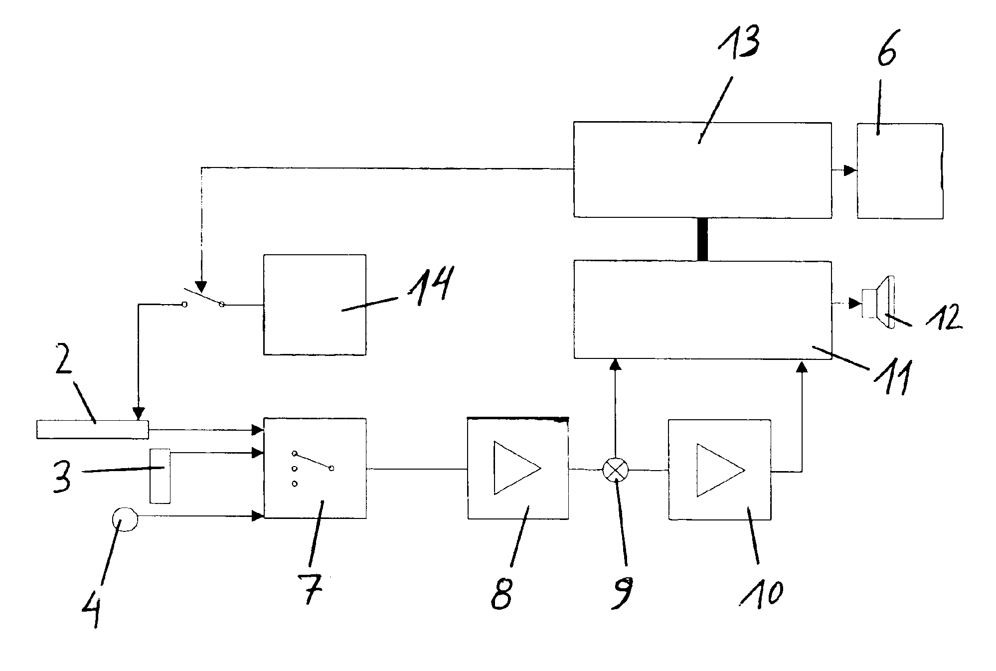
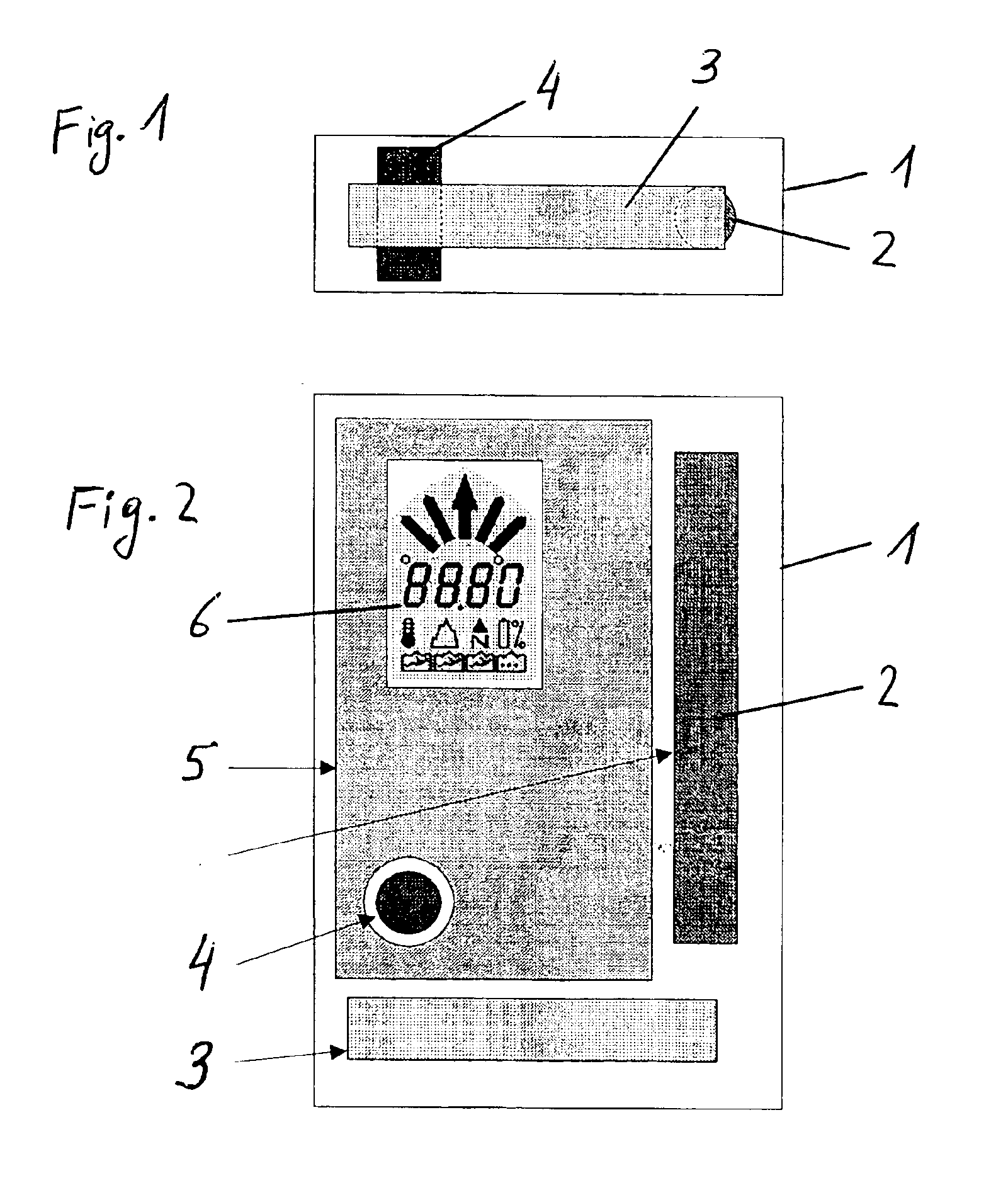
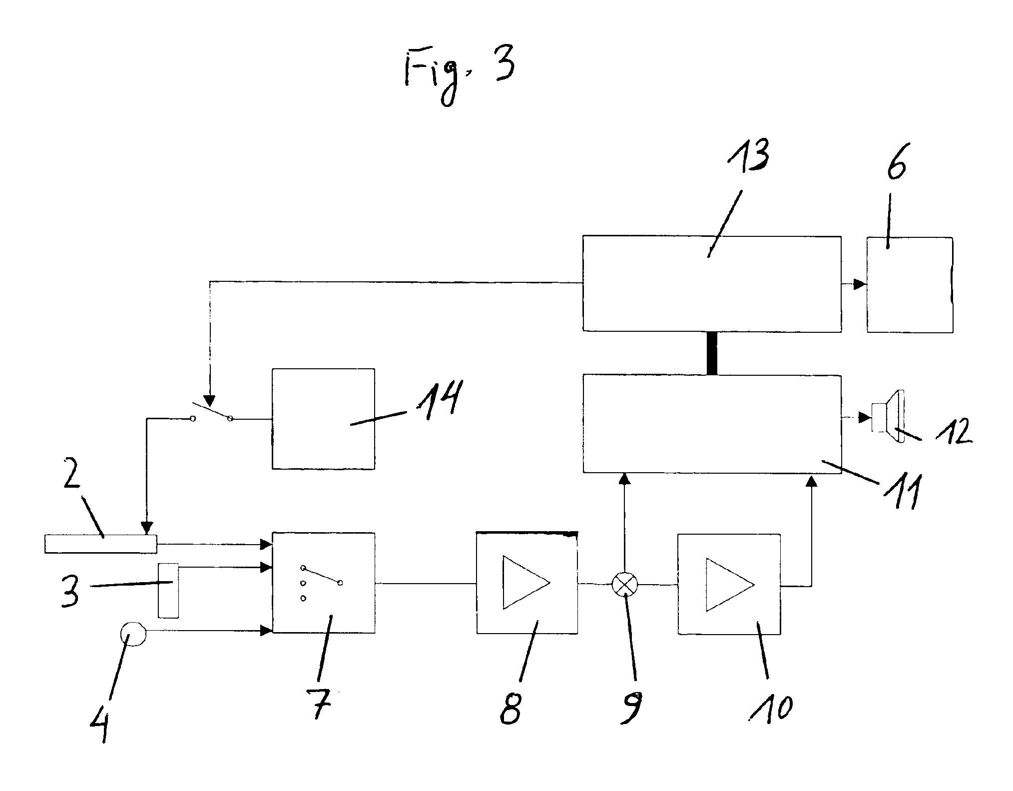
[0024]Three ferrite antennas 2, 3 and 4 are disposed in the housing 1 of the inventive locating device. The antennas are preferably orthogonal to one another and of various lengths to make possible the compact traditional dimensioning of the housing 1 in terms of its shape. The shortest antenna 4 is maximally half as long as the longest antenna 2 of the locating device, while the two longer antennas 2 and 3 have lengths of approximately 8 cm or 6 cm. The length of antenna 4 is preferably approximately a quarter-length of the longest antenna 2, which is approximately 2 cm in absolute numbers.

[0025]As can seen in FIG. 2, the two longer antennas 2 and 3 lie essentially parallel to the lateral side or the face of a printed circuit board 5, which contains receiving and transmitting electronics and on the optical display unit 6 attached to said printed circuit board as well. Symbols are provided on the display unit 6 that may be triggered to determine direction and distance to the incomin...


PUM


Abstract

A locating device, particularly for locating trapped victims under avalanches, under debris or under collapsed buildings, equipped with a receiving unit (6-13) for signals from transmitters and preferably a transmitter (13, 14), as well as optical (6) and/or acoustic (12) display units, whereby the receiving unit is connected to three preferably orthogonally arranged ferrite rod antennas (2, 3, 4). All antennas (2, 3, 4) are disposed in a compact housing (1) together with the receiving unit (6-13) and preferably also the transmitter (13, 14) to ensure accurate locating of the trapped victim across the largest range possible at compact design whereby one antenna (4) is of substantially shorter length than the two other antennas (2, 3). The receiving unit is provided with a DSP module (11) for incoming signals of the antennas (2, 3, 4).

Description

BACKGROUND OF THE INVENTION[0001]1. Field of the Invention[0002]The present invention relates to a locating device, particularly for locating trapped victims under avalanches, under debris or under collapsed buildings, including a receiving unit for signals from transmitters, preferably a transmitter connected to three preferably orthogonally arranged ferrite rod antennas, optical and / or acoustic display units, as well as a method for the operation of a locating device, particularly for locating trapped victims under avalanches, under debris or under collapsed buildings, whereby incoming signals of one or several transmitters are monitored by a receiving unit.[0003]2. The Prior Art[0004]Current portable devices for locating trapped victims are equipped with devices to detect and display the magnitude and possibly the direction of the magnetic field strength of a transmitter. This displayed information is used to advance toward the trapped victim along field lines. In most cases, one...

Claims


Application Information

Patent Timeline
Patent Type & Authority Patents(United States)
IPC IPC(8): A63B29/00A63B29/02G01S3/04G01S3/14G01S3/02G01V3/15
CPCA63B29/021G01S3/043G01S3/046G01S3/14G01V3/15
Inventor SACKL, RUDOLF
Owner SEIDEL ELEKTRONIK NFG
Why Eureka
Try Eureka