
Scan circuit and method for keyboard

a keyboard and circuit technology, applied in the direction of instruments, coding, pulse techniques, etc., can solve the problems of two inputs being pressed synchronously, the keyboard scan circuit might fail, and the error result of the keyboard scan might appear, so as to increase the simultaneous receiving input of the keyboard, increase the cost, and increase the detection of input terminals

Inactive Publication Date: 2005-11-01
WINBOND ELECTRONICS CORP
View PDF5 Cites 3 Cited by
  • Summary
  • Abstract
  • Description
  • Claims
  • Application Information

AI Technical Summary

Benefits of technology

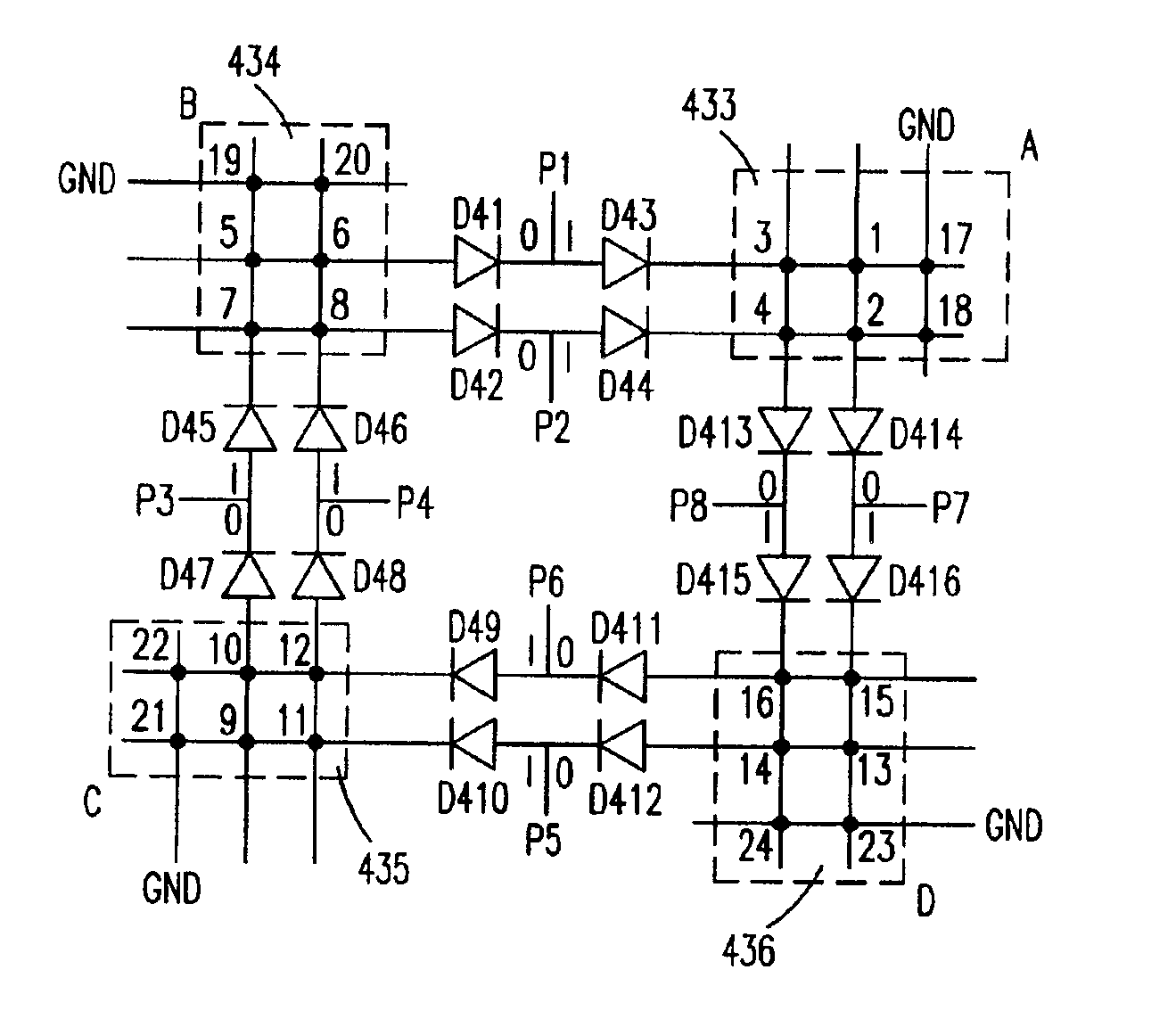
[0006]It is another object of the present invention to provide a scan circuit and a method for increasing the detectable input terminals and synchronously detectable input terminals in a keyboard.
[0007]It is another further object of the present invention to provide a three-dimensional circuit for being distinct from the traditional flat circuit to increase the simultaneous receiving inputs of a keyboard, but not to increase the cost.
[0009]Preferably, the scan circuit further includes a ground terminal for forming the rectangular matrices by means of cross-linking the keyboard input / output ports therewith, so as to increase the number the detectable input terminals.

Problems solved by technology

If a third input is received from the keyboard, an error result of the keyboard scan might appear.
But there exists a defect in the keyboard scan circuit.
The defect is that only two inputs can be pressed synchronously.
Thus there brings an error decision.

Method used


Image

  • Scan circuit and method for keyboard
  • Scan circuit and method for keyboard
  • Scan circuit and method for keyboard

Examples


Embodiment Construction

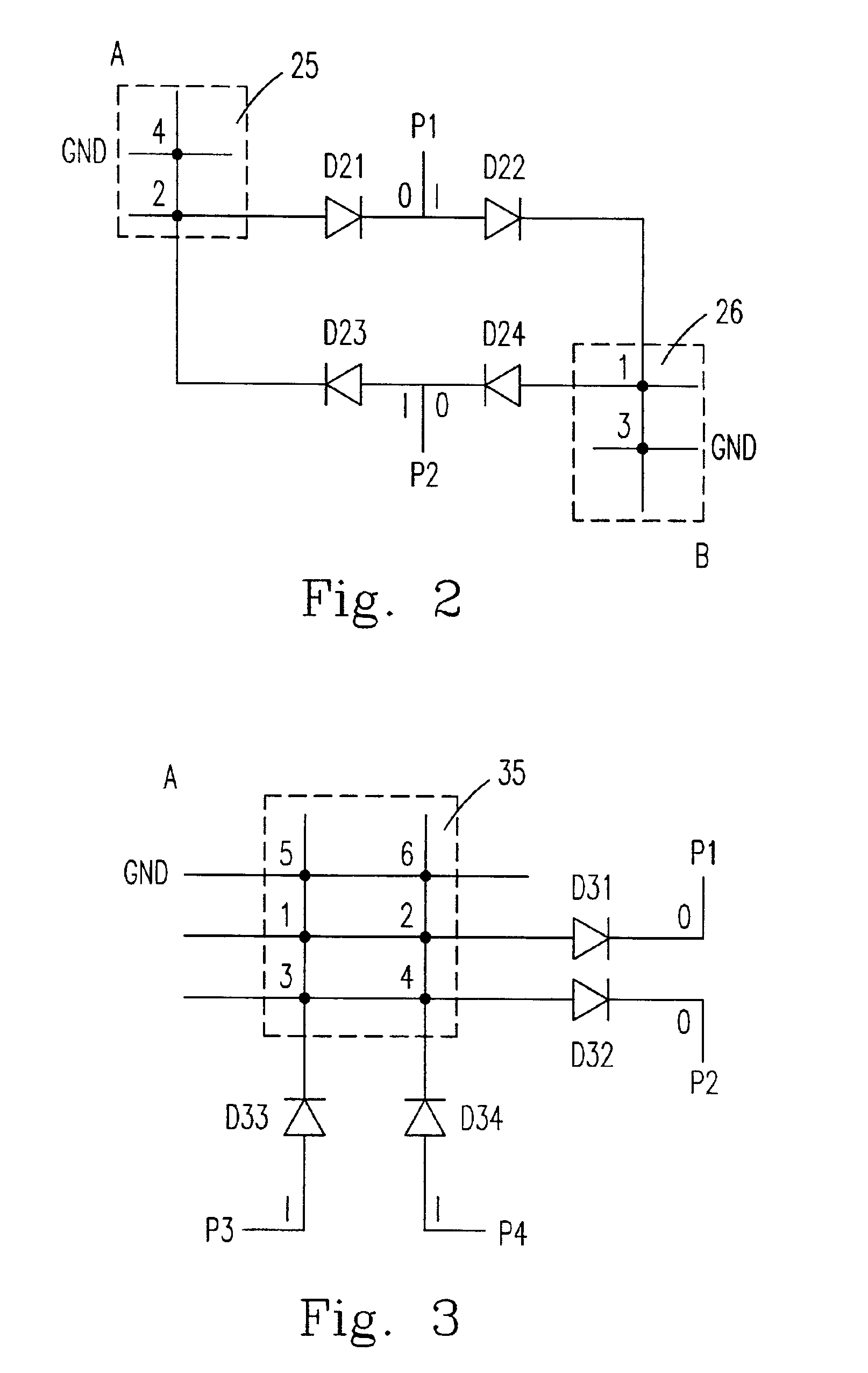
[0032]Please refer to FIG. 2. FIG. 2 shows a schematical view of the smallest scan cell circuit in the keyboard scan circuit. The scan cell is constituted by two keyboard input / output ports (P1 and P2), each of which can be selected from a group consisting of an input mode, an output mode, and a floating mode, and four diodes (D21˜D24) to form two rectangular matrices (25 and 26) in which there are four detectable input terminals (1˜4) and two synchronously detectable input terminals (1 and 2) therein.

[0033]Assuming that the scan time is separated to T1, T2, T3, and T4, P1 is set in the output mode, and P2 is set in the input mode while the times are at T1 and T2. Consequently, the matrix A (25) will be scanned firstly, so that the terminal 4 will be detected at T1 and the terminal 2 will be detected at T2. Continuously, P1 is set in the input mode, and P2 is set in the output mode while the times are at T3 and T4. Then, the matrix B (26) will be scanned at this moment, so that the ...


PUM


Abstract

A keyboard scan circuit for a device receiving plural inputs simultaneously is provided. The scan circuit includes a plurality of keyboard input / output ports, each of which can be selected from a group consisting of an input mode, an output mode, and a floating mode for receiving one of a plural inputs, a plurality of rectangular matrices including a plurality of detectable input terminals and a plurality of synchronously detectable input terminals and formed by means of cross-linking the keyboard input / output ports, and a plurality of current-isolating elements electrically connected between the keyboard input / output ports and the rectangular matrices for mutually isolating signals of the rectangular matrices.

Description

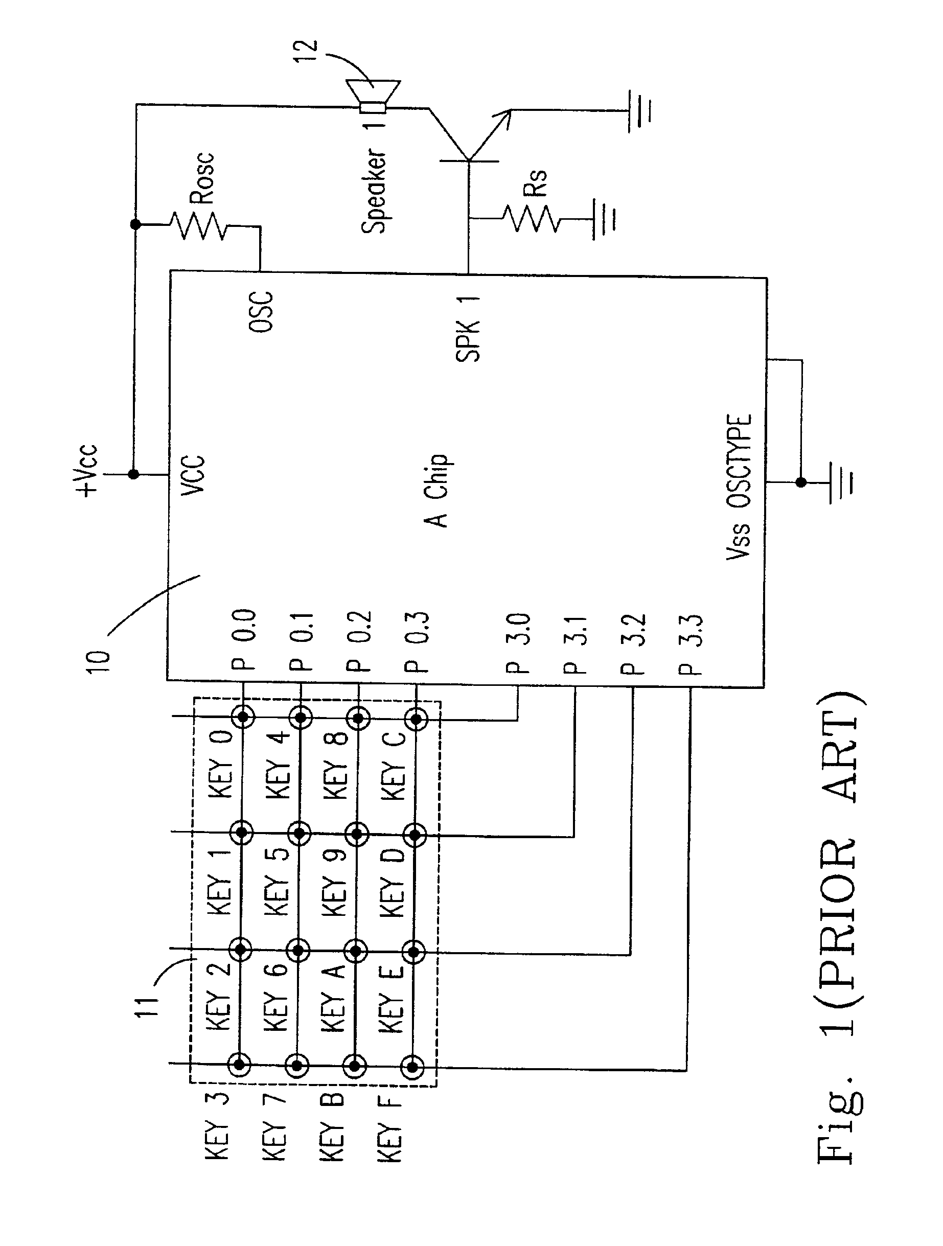
FIELD OF THE INVENTION[0001]This invention relates to a scan circuit and a method for a keyboard, and more particularly to a scan circuit and a method for a device synchronously receiving inputs.BACKGROUND OF THE INVENTION[0002]Nowadays, input / output ports of a microprocessor chip are widely used in a maximal matrix keyboard scan operation of a keyboard. On the chip, the input / output ports are used to execute the maximal matrix keyboard scan for controlling keys of the electronic organ. But under this condition, the keyboard input / output ports only can receive two inputs at the same time. If a third input is received from the keyboard, an error result of the keyboard scan might appear.[0003]Please refer to FIG. 1. FIG. 1 shows the schematical view of the circuit of the prior art. FIG. 1 shows a 4×4 matrix 11 which is formed by means of cross-linking eight input / output ports, and thus there are sixteen inputs in the matrix 11. When any one of the sixteen inputs is pressed, the corres...

Claims


Application Information

Patent Timeline
IPC IPC(8): H03M11/20H03M11/00
CPCH03M11/003H03M11/20
Inventor FENG, CHING-HSIANG
Owner WINBOND ELECTRONICS CORP
Learn More