Solar thermoelectric power generation system

A technology of thermoelectric power generation and solar panels, which is applied in the directions of solar thermal power generation, wind power generation, and mechanical power generation with solar energy, and can solve the problems of wind power generation fluctuation and intermittency

Inactive Publication Date: 2013-08-21
王广武
View PDF1 Cites 54 Cited by
  • Summary
  • Abstract
  • Description
  • Claims
  • Application Information

AI Technical Summary

Problems solved by technology

3. A vertical wind power generation device and an auxiliary motor drive device are installed on the output shaft of the gas turbine, and the direct current generated by solar photothermal conversion is used to drive the wind power generation to assist the rotation of the DC motor, which solves the fluctuation of the generated electricity due to the randomness of the wind power. Intermittent problems, realize the complementarity of solar energy and wind energy resources, realize the sharing of energy storage devices and transmission systems, save construction costs, and improve power generation efficiency

Method used


Image

  • Solar thermoelectric power generation system
  • Solar thermoelectric power generation system
  • Solar thermoelectric power generation system

Examples


Embodiment 1

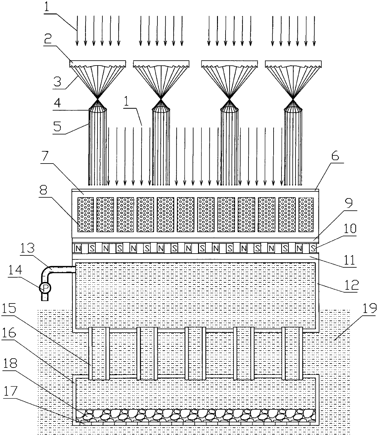
[0019] The cross-sectional structure diagram of the solar thermoelectric power generation system is as follows: figure 1 As shown, among them: 1 is the sunlight, 2 is the strip Fresnel condenser, 3 is the reflected light, 4 is the collimating lens, 5 is the concentrated light, 6 is the solar heat absorbing coating, 7 is the metal light-to-heat conversion device , 8 is the phase change energy storage material, 9 is the hot end of the thermoelectric power generation device, 10 is the semiconductor thermoelectric chip, 11 is the cold end of the thermoelectric power generation device, 12 is the upper water tank, 13 is the drain pipe, 14 is the guide pump, and 15 is the connecting pipe 16 is the lower water tank, 17 is the water inlet of the lower water tank, 18 is filter sand, and 19 is lake water or river water or sea water or pond water.

[0020] When in use, the sunlight 1 is irradiated on the strip Fresnel condenser 2, the reflected light 3 is irradiated on the collimator lens...

Embodiment 2

[0022] The combined cross-sectional structure diagram of the solar thermoelectric power generation system and the closed gas turbine power generation system is shown in figure 2As shown, wherein: 20 is sunlight, 21 is a strip Fresnel condenser, 22 is reflected light, 23 is a collimating lens, 24 is concentrated light, 25 is a solar heat absorbing coating, and 26 is a metal light-to-heat conversion device , 27 is the liquid circulation water of the metal photothermal conversion device, 28 is the liquid circulation water output pipe, 29 is the phase change energy storage material storage chamber, 30 is the phase change energy storage material, 31 is the hot end of the thermoelectric power generation device, 32 is the semiconductor temperature difference Chip, 33 is the cold end of the thermoelectric power generation device, 34 is the upper water tank, 35 is the drain pipe, 36 is the guide pump, 37 is the connecting pipe, 38 is the lower water tank, 39 is the water inlet hole of ...


PUM


Abstract

A solar thermoelectric power generation system comprises a solar thermoelectric power generation system body, a concentrated solar device, a metal photothermal conversion device, a water circulating cooling system and a solar heat absorption coating. Sunlight and concentrated sunlight can irradiate on the metal photothermal conversion device which is coated by the solar heat absorption coating, the solar heat absorption coating converts light energy into heat energy, and then the heat energy is transmitted to the metal photothermal conversion device, the metal photothermal conversion device transmits the heat energy to a hot end of a thermoelectric power generation device, a cold end of the thermoelectric power generation device is cooled by the seawater or river water or lake water or pond water or underground water circulating cooling system, and the solar thermoelectric power generation system body which is composed of the hot end of the thermoelectric power generation device and the cold end of the thermoelectric power generation device can convert heat into electrical energy.

Description

technology field; [0001] The invention relates to a solar thermoelectric power generation system, a combined solar thermoelectric power generation system and a gas turbine power generation system, and a solar thermoelectric power generation system combined with a solar cell power generation system. Background technique: [0002] When using thermoelectric solar cells to generate electricity, it is necessary to maintain a large enough temperature difference between the two media of the battery to obtain large output power. Since the energy density of solar energy is small and cannot meet the temperature difference requirements of semiconductor thermoelectric cells, solar energy is limited to heat engine power generation and solar cell power generation. application, and the use of thermoelectric batteries to generate electricity can solve the problem of high cost of solar power generation technology. CN200520120563.0 "Concentrating and heat-collecting solar thermoelectric power ...

Claims


Application Information

Patent Timeline
Patent Type & Authority Applications(China)
IPC IPC(8): H02N11/00F03G6/06F03D9/00
CPCY02E10/46Y02E10/72
Inventor 王广武
Owner 王广武
Why Eureka
Try Eureka