Method and apparatus for sparkle reduction by reactive and anticipatory slew rate limiting

a technology of reactive and anticipatory slew rate and sparkle reduction, applied in the field of video systems, can solve the problems of inability to have the imager absorb light, the imager will get hot, and the brightness of the local area is substantial, and achieves the effect of reducing the interdependence of adjacent pixels

Inactive Publication Date: 2005-11-01
INTERDIGITAL CE PATENT HLDG
View PDF11 Cites 4 Cited by
  • Summary
  • Abstract
  • Description
  • Claims
  • Application Information

AI Technical Summary

Benefits of technology

[0013]The method can further comprise the steps of: further dividing the input signal into a medium brightness signal having brightness levels between the high and low brightness level signals; limiting signal transients between brightness levels of the medium brightness signal to further reduce adjacent pixel interdependence; and, combining the slew rate limited and finite response filtered signal with the high and low brightness signals. The medium brightness signal can be slew rate limited and finite response filtered. Different slew rates and different finite filter responses can be applied to the medium and low brightness signals.

Problems solved by technology

It should be noted that it is undesirable to have the imager absorbing light because it can get too hot.
The imager will get hot due to some spurious amount of absorption.
This distortion results in a substantial local increase in brightness.
This is a particular problem when the pixel is supposed to be dark, but is usually an insignificant problem when the pixels are intended to be bright since the pixels are not very different in voltage so the fringing field is not that great.
Often, a large difference in voltage between adjacent pixels is needed.
Because of the particular manufacturing process used for many imagers, horizontally adjacent pixels suffer more from the fringing field problem.

Method used


Image

  • Method and apparatus for sparkle reduction by reactive and anticipatory slew rate limiting
  • Method and apparatus for sparkle reduction by reactive and anticipatory slew rate limiting
  • Method and apparatus for sparkle reduction by reactive and anticipatory slew rate limiting

Examples


Embodiment Construction

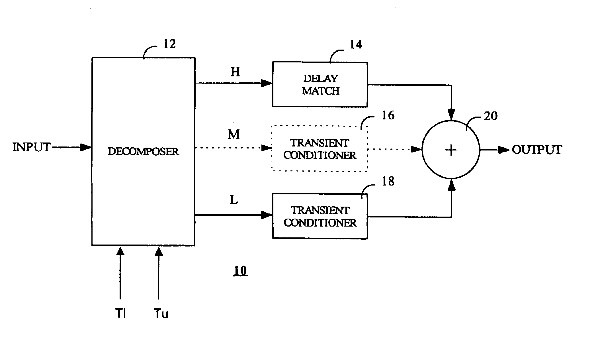
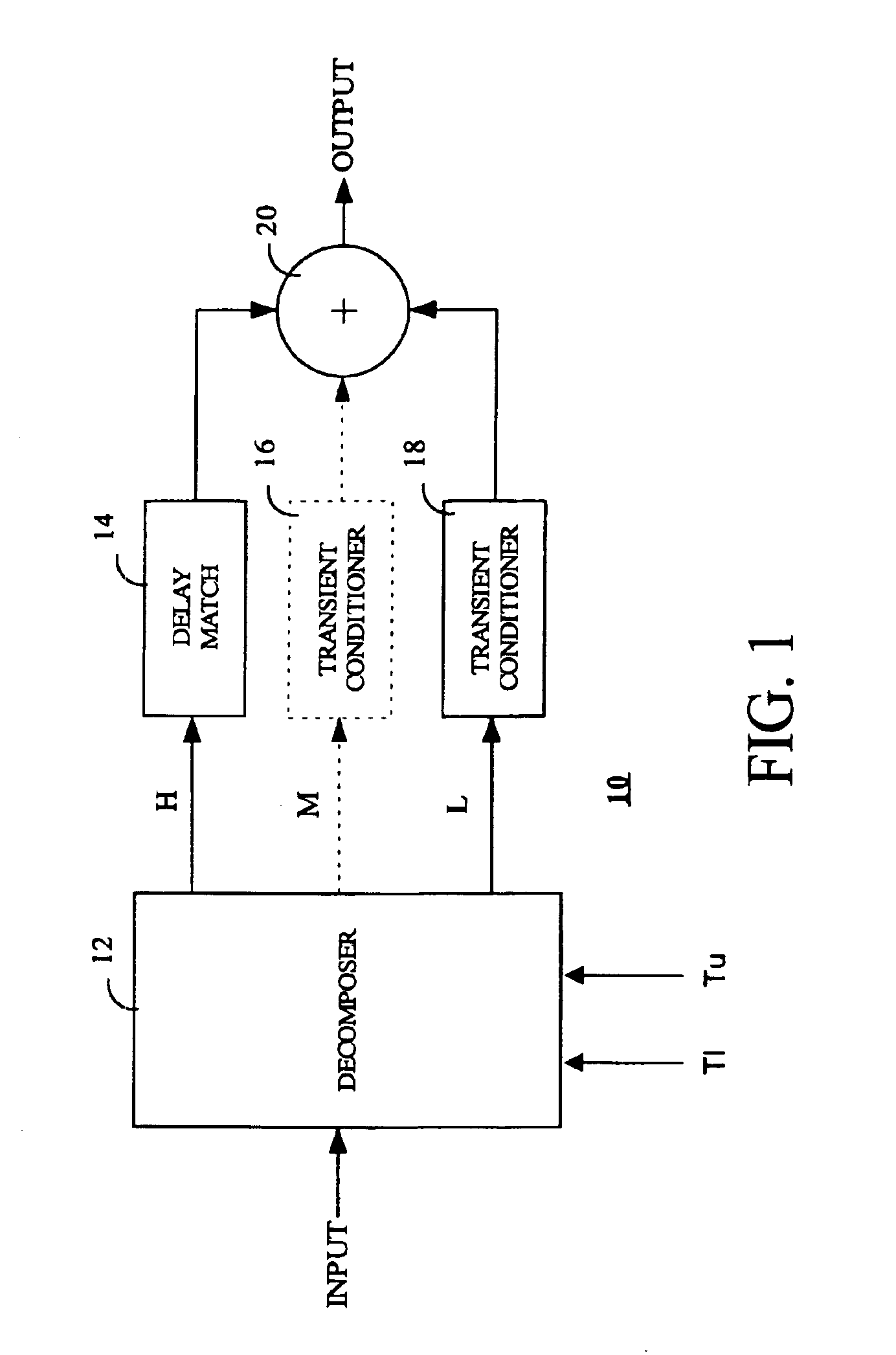
[0018]Reducing the difference in brightness between adjacent pixels when they are dark, but not when they are bright can resolve the sparkle problem previously described. A device called a decomposer 12 on the input divides the input signal into at least two signals on a circuit 10 used to reduce adjacent pixel interdependence in liquid crystal displays as shown in FIG. 1. It should be understood that Sparkle or declination errors can also be considered a subset of a broader phenomenon known as adjacent pixel interdependence. It should be noted that the present invention is particularly useful for liquid crystal on silicon (LCOS) displays but is not necessarily limited thereto. The decomposer 12 serves as an amplitude discriminator for the input signal which is preferably an eight (8) bit video signal that preferably carries the desired brightness of one color component (Red, Green, or Blue).

[0019]The input signal is decomposed in a manner that enables obtaining the original signal ...


PUM

PropertyMeasurementUnit
voltageaaaaaaaaaa
voltageaaaaaaaaaa
voltageaaaaaaaaaa

Abstract

A circuit (10) for reducing errors due to adjacent pixel interdependence in a liquid crystal display includes a decomposer (12) for dividing an input signal into a plurality of signals having at least a high brightness signal and at least one low brightness signal, a delay match circuit (14) for the high brightness signal to provide a delay high brightness signal, one or more transient conditioner circuits (16 and/or 18) for processing the at least one low brightness signal to provide at least one transient conditioned low brightness signal, and a combiner (20) for combining the delay matched high brightness signal with the at least one transient conditioned low brightness signal to provide an output signal having reduced sparkle artifacts.

Description

CROSS REFERENCE TO RELATED APPLICATIONS[0001](not applicable)BACKGROUND OF THE INVENTION[0002]1. Field of the Invention[0003]This invention relates to the field of video systems utilizing a liquid crystal display (LCD), and in particular, to video systems utilizing normally white liquid crystal on silicon imagers.[0004]2. Description of Related Art[0005]Liquid Crystal on Silicon (LCOS) can be thought of as one large liquid crystal placed over a silicon wafer. The silicon wafer is divided into an incremental array of tiny plates. A tiny incremental region of the liquid crystal is influenced by the electric field generated by each tiny plate and a common plate. Each such tiny plate and corresponding liquid crystal region are together referred to as a cell of the imager. Each cell corresponds to an individually controllable pixel. Each tiny plate is also a mirror for reflecting back a cell's light. A common plate electrode is disposed on the other side of the liquid crystal.[0006]The d...

Claims


Application Information

Patent Timeline
Patent Type & Authority Patents(United States)
IPC IPC(8): G09G3/36G09G3/20G02F1/133
CPCG09G3/3648G09G2320/02G09G2320/0209G02F1/133
Inventor WILLIS, DONALD HENRY
Owner INTERDIGITAL CE PATENT HLDG
Why Eureka
Try Eureka