Check patentability & draft patents in minutes with Patsnap Eureka AI!

Identifying and synchronizing permuted channels in a parallel channel bit error rate tester

a technology of parallel channel and which is applied in the field of parallel channel bit error rate tester, can solve the problems of lack of synchronization, only appearing errors resulting from cross-talk between two channels, and lack of synchronization between multiplexers and demultiplexers

Inactive Publication Date: 2005-11-01
AGILENT TECH INC
View PDF5 Cites 15 Cited by
  • Summary
  • Abstract
  • Description
  • Claims
  • Application Information

AI Technical Summary

Benefits of technology

[0010]The present invention is a test system that includes a generator and an analyzer acting cooperatively to test a device having a plurality of device communication channels. The device has a plurality of inputs and corresponding outputs, each input routing data to a corresponding one of the outputs. The generator includes a plurality of test pattern channels. Each test pattern channel includes a pattern generator reference memory for storing a test sequence to be communicated to an input of the device and a circuit for repetitively sending the test sequence to one of the channels of the device. The analyzer includes a plurality of analyzer channels. Each analyzer channel includes an input for receiving a channel input signal, an analyzer pattern reference memory for storing a reference pattern utilized by that analyzer channel, and a compare circuit for comparing that reference pattern with a signal received on one of the communication channels of the device. The compare circuit provides a bit error value indicative of the extent of mismatch between the reference pattern and the received signal. The test system includes a program for operating the analyzer and generator that provides a mapping of the input channels of the device to the output channels of the device. The program (a) causes one of the generator and the analyzer to load the reference memories included therein with a set of mutually exclusive mapping test patterns such that each reference memory has a unique test pattern stored therein; (b) causes the other of the generator and the analyzer to load one of the set of mapping test patterns into all of the memories; (c) causes each analyzer channel to compare the channel input signal received on that channel with the reference pattern stored in that channel; and (d) determines if one of the bit error values provided by the compare circuits is less than a bit error threshold value, and if so, maps the analyzer channel for which the bit error value is less than the bit error threshold value to the generator channel having the same mapping test pattern. The test system repeats (a)–(d) with a different one of the mapping test patterns being loaded into the memories in (b) until the controller is able to assign all of the input channels to their corresponding output channels. The test system can also utilize information about the device being tested in conjunction with one or more channel mappings to map the remainder of the channels once one or more corresponding channels have been mapped using the algorithm discussed above. In the preferred embodiment of the present invention, the reference memories of the generator rather than the analyzer are loaded with the set of mutually exclusive mapping test patterns during the input to output channel mapping operation. After the test system has mapped the input and output channels of the device, the generator loads a set of bit error test patterns into the reference memories in the controller and to proceed with bit error testing.

Problems solved by technology

In addition, such testers can detect errors that are only present when a number of channels are operating simultaneously.
For example, errors resulting from cross-talk between two channels only appear when there is data on both channels.
This can occur if the phases of the various multiplexers and demultiplexers are not properly synchronized.
This lack of synchronization can result from the multiplexers not being synchronized with each other, the demultiplexers not being synchronized with each other, or the demultiplexers as a group not being synchronized with the multiplexers as a group.
An unknown time delay through the communication link often results in a lack of synchronization between the multiplexers and the demultiplexers.
Each of these conditions can result in a rearrangement of the data patterns.
These data rearrangements pose a problem because bit error-rate testing is based on knowledge of the data pattern expected in each channel by the error analyzer.
If the expected data pattern is rearranged, then the test is useless unless this rearrangement can be identified.
While communications multiplexers that are synchronized to each other (and also have synchronized phases) can be constructed, it is far less practical to construct communications demultiplexers that can be synchronized to each other and share a common internal phase.
First, demultiplexers often recover the data clock from the data passing therethrough.
These circuits typically initialize in a random state relative to the multiplexers, and hence, will not, in general, be properly synchronized.
Secondly, the unavoidable time delay of propagating the data stream through the communication link connecting the multiplexers and demultiplexers results in the data arriving with an unknown phase relative to that of the multiplexers.

Method used


Image

  • Identifying and synchronizing permuted channels in a parallel channel bit error rate tester
  • Identifying and synchronizing permuted channels in a parallel channel bit error rate tester
  • Identifying and synchronizing permuted channels in a parallel channel bit error rate tester

Examples


Embodiment Construction

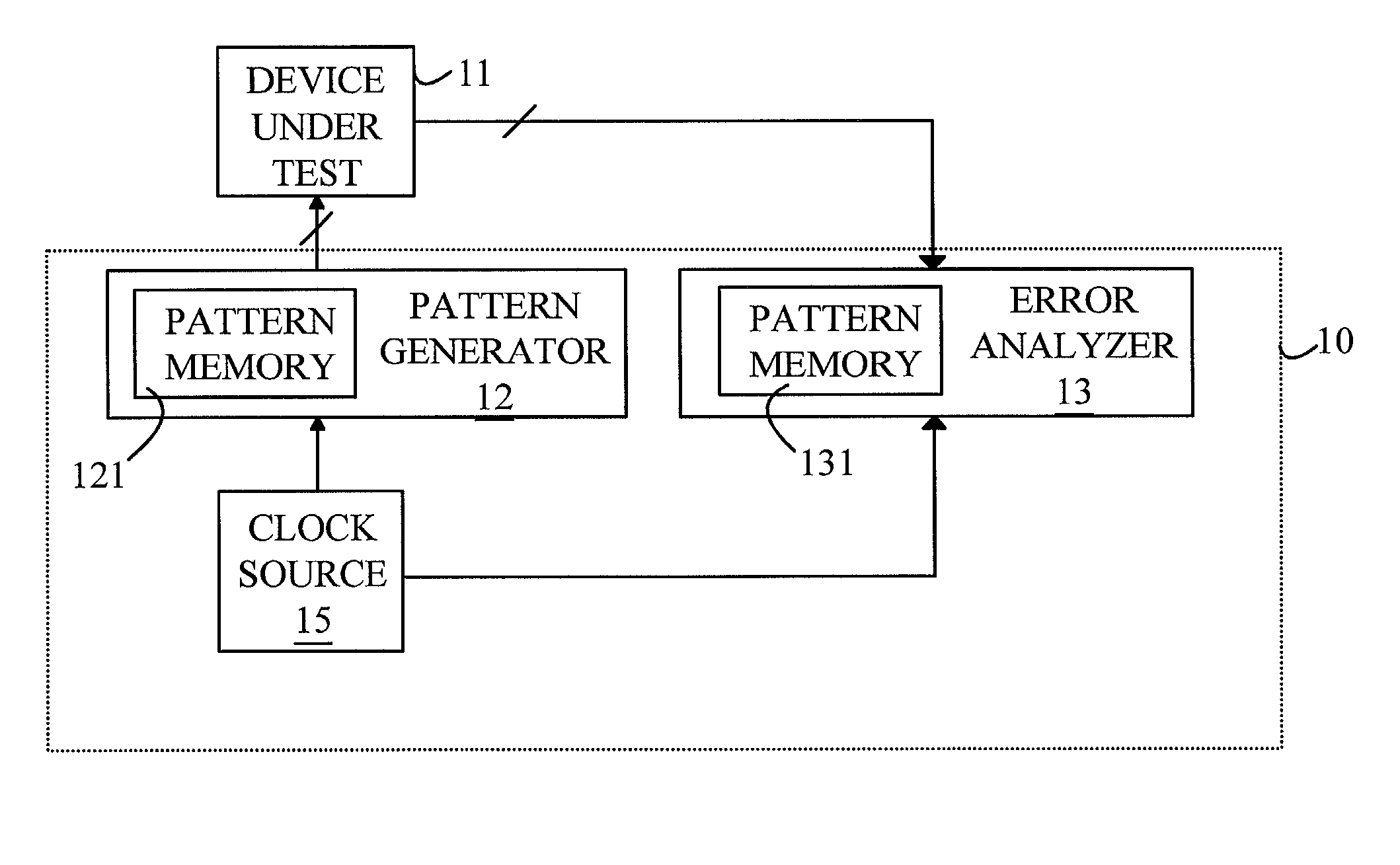
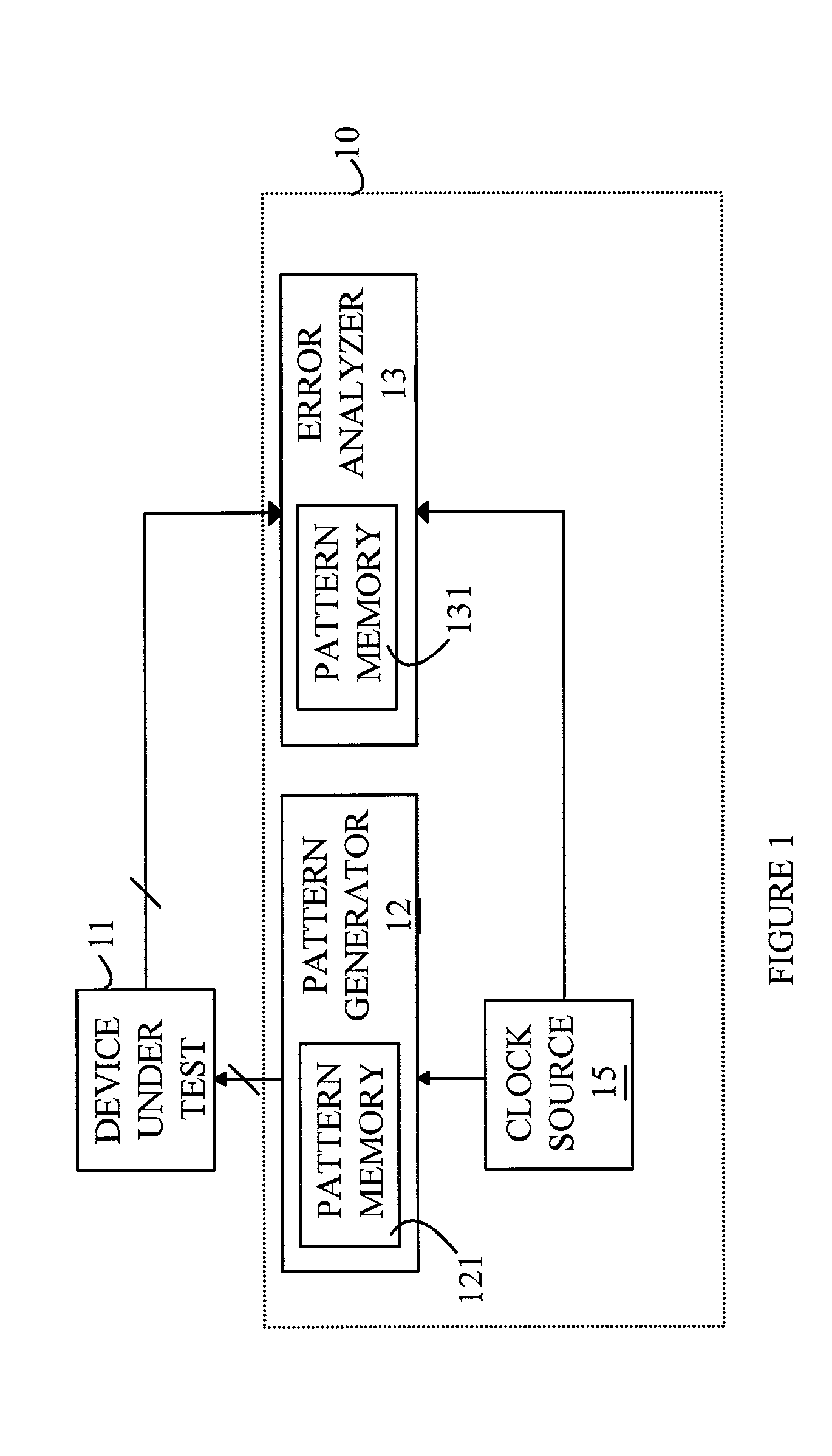
[0015]The manner in which the present invention provides its advantages can be more easily understood with reference to FIG. 1, which is a schematic drawing of parallel channel bit error rate tester 10 connected to a device under test (DUT) 11. In its simplest form, parallel channel bit error rate tester 10 consists of a pattern generator 12 and an error analyzer 13 that are connected through DUT 11. The pattern generator generates a predetermined pattern for input to DUT 11. This pattern is stored in a pattern memory 121. Analyzer 13 compares the received data to the known pattern, which is stored in pattern memory 131 and measures the bit error (BER). The pattern generator has a clock source 15, which triggers the generation of the test data. To conduct bit error rate testing, error analyzer 13 must be clocked at the same rate as the incoming data stream. This is accomplished either by triggering the error analyzer and pattern generator from a common clock source, or by having the...


PUM


Abstract

A test system that includes a generator and an analyzer acting cooperatively to test a device having a plurality of device communication channels. The device has a plurality of inputs and corresponding outputs, each input being connected to a corresponding one of the outputs. The correspondence between the input and output channels may change if the device is turned off and on or if the device is not actively sending data from the inputs to the outputs. The test system determines a mapping between the device inputs and outputs prior to performing bit error rate testing utilizing a mapping test pattern. The test system can then switch to a bit error rate test pattern without causing the device to drift such that the correspondence between the input and output channels is lost.

Description

FIELD OF THE INVENTION[0001]The present invention relates to the testing of high-speed communication channels, and more particularly, to an improved parallel channel bit error rate tester and method for using the same to test such channels.BACKGROUND OF THE INVENTION[0002]A parallel channel bit error rate tester is normally used in communication systems having a number of separate channels. Such testers provide a means for testing many channels simultaneously, and hence, reduce the time needed to test a communication system. In addition, such testers can detect errors that are only present when a number of channels are operating simultaneously. For example, errors resulting from cross-talk between two channels only appear when there is data on both channels. A parallel channel bit error rate tester typically includes a pattern generator for generating signals on each of the channels to be tested and an analyzer that examines the signals received at the terminus of the communication ...

Claims


Application Information

Patent Timeline
Patent Type & Authority Patents(United States)
IPC IPC(8): H04L1/24G01R31/28H04B3/46H04J3/00H04L1/00
CPCH04L1/242
Inventor ABRAMOVITCH, DANIEL Y.WEINSTEIN, MICHAEL J.PLITSCHKA, HEINZ R.
Owner AGILENT TECH INC
Features
  • R&D
  • Intellectual Property
  • Life Sciences
  • Materials
  • Tech Scout
  • Unparalleled Data Quality
  • Higher Quality Content
  • 60% Fewer Hallucinations
Learn More