Sweep method using digital signals

a digital signal and sweep method technology, applied in the direction of pulse technique, amplitude demodulation, transmission monitoring, etc., can solve the problems of affecting the service of catv subscribers, temperature-related drift, etc., and achieve high resolution

Active Publication Date: 2005-11-01
VIAVI SOLUTIONS INC
View PDF15 Cites 54 Cited by
  • Summary
  • Abstract
  • Description
  • Claims
  • Application Information

AI Technical Summary

Benefits of technology

[0012]The present invention satisfies the above-stated need, as well as others, by providing a method of determining a frequency response of a channel by obtaining a relative frequency response of the channel and an overall channel signal strength. The present method combines these obtained values to generate an absolute level frequency response. The use of an absolute level frequency response allows the frequency response for the measured channel to be combined with frequency response information from other channels, digital or analog, to obtain a system frequency response of high resolution and which may be accomplished in a non-invasive manner.

Problems solved by technology

Although a digital communication system can be made essentially error-free, the transmission over a physical medium is still susceptible to misalignment, temperature-related drift, and induced noise and impedance variation.
A problem with the conventional frequency sweep test is that it disrupts service to the CATV subscribers because the injected test signal interferes with their reception of the corresponding channel.
Such analog sweep systems are not applicable to digital television signals, which do not include such pulses (e.g., sync pulses).
Moreover, such prior art systems often provide limited resolution, typically a single measurement per channel.
However, the method therein described only computes an estimate of a system response that is then deconvolved to isolate particular components.
In addition, that method requires that an impulse be fed into the system and, thus, can be invasive.

Method used


Image

  • Sweep method using digital signals
  • Sweep method using digital signals
  • Sweep method using digital signals

Examples


Embodiment Construction

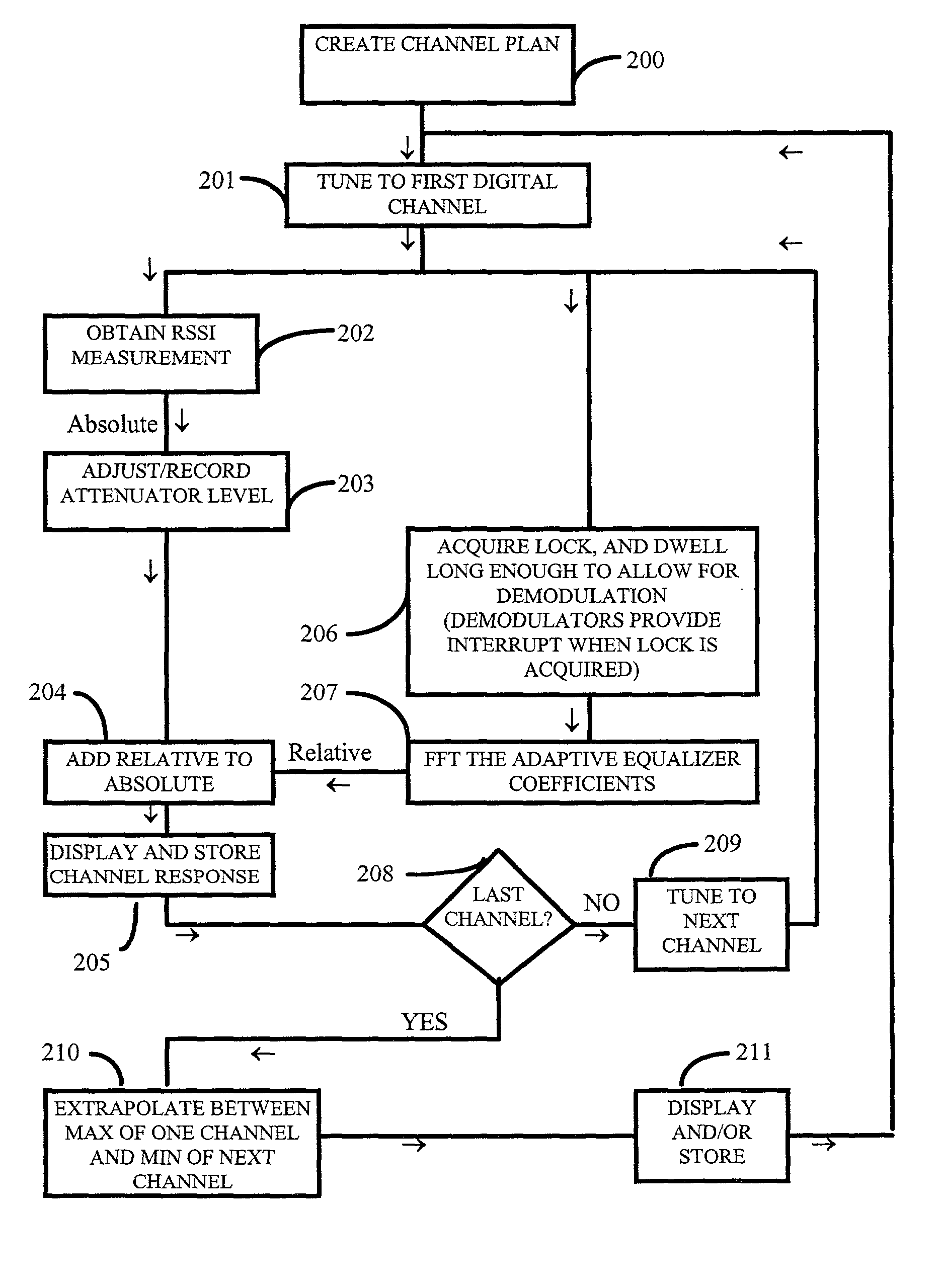
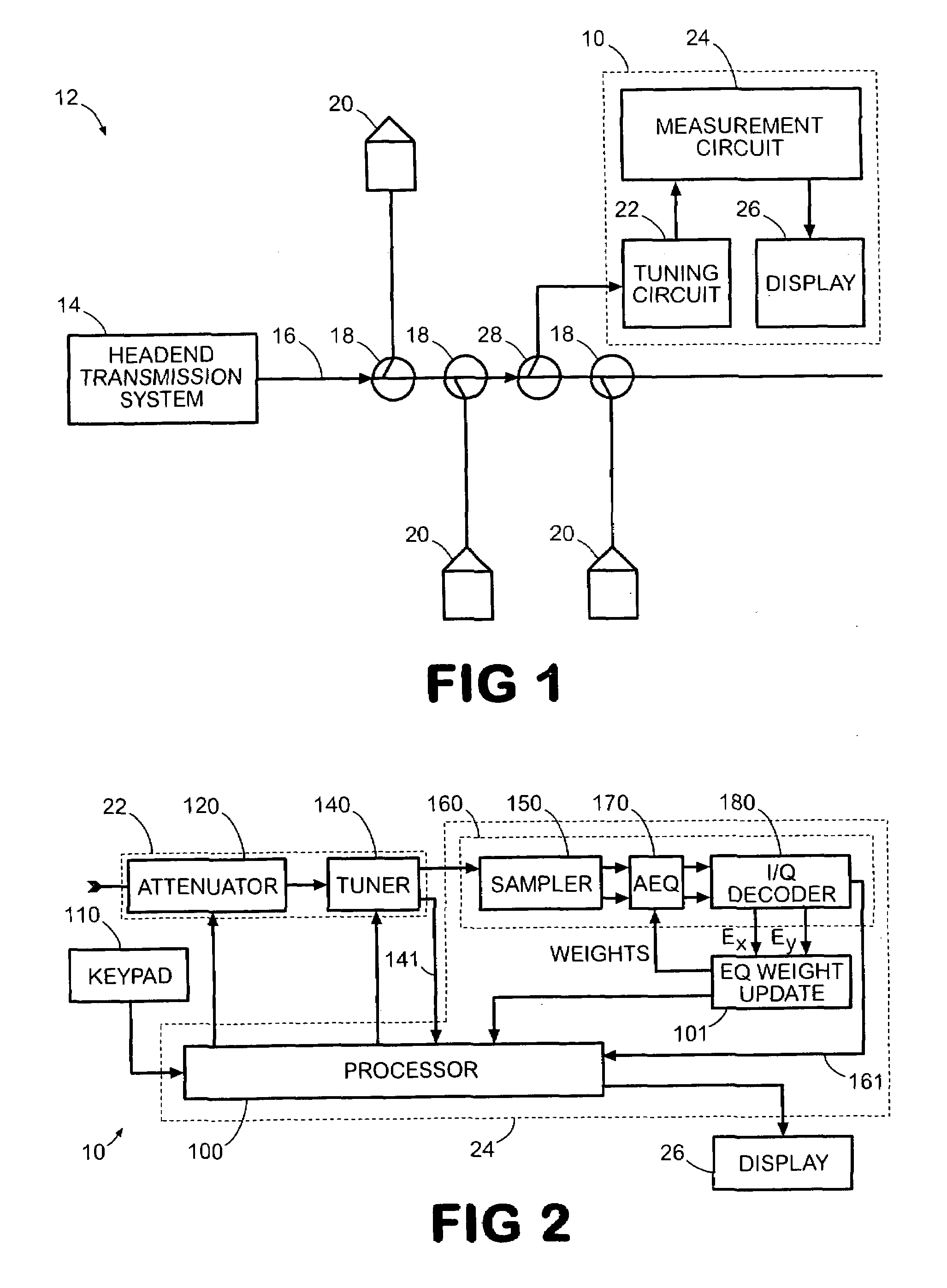
[0023]FIG. 1 shows a frequency response measurement device 10 according to the present invention implemented within a communication system 12. The communication system 12 comprises a CATV distribution system and includes a headend transmission system 14, a distribution network 16, and a plurality of splitters 18 disposed along the distribution network 16. It will be noted that the communication system 12 is shown in greatly simplified form, although it is representative of the general configuration of all terrestrial CATV distribution systems.

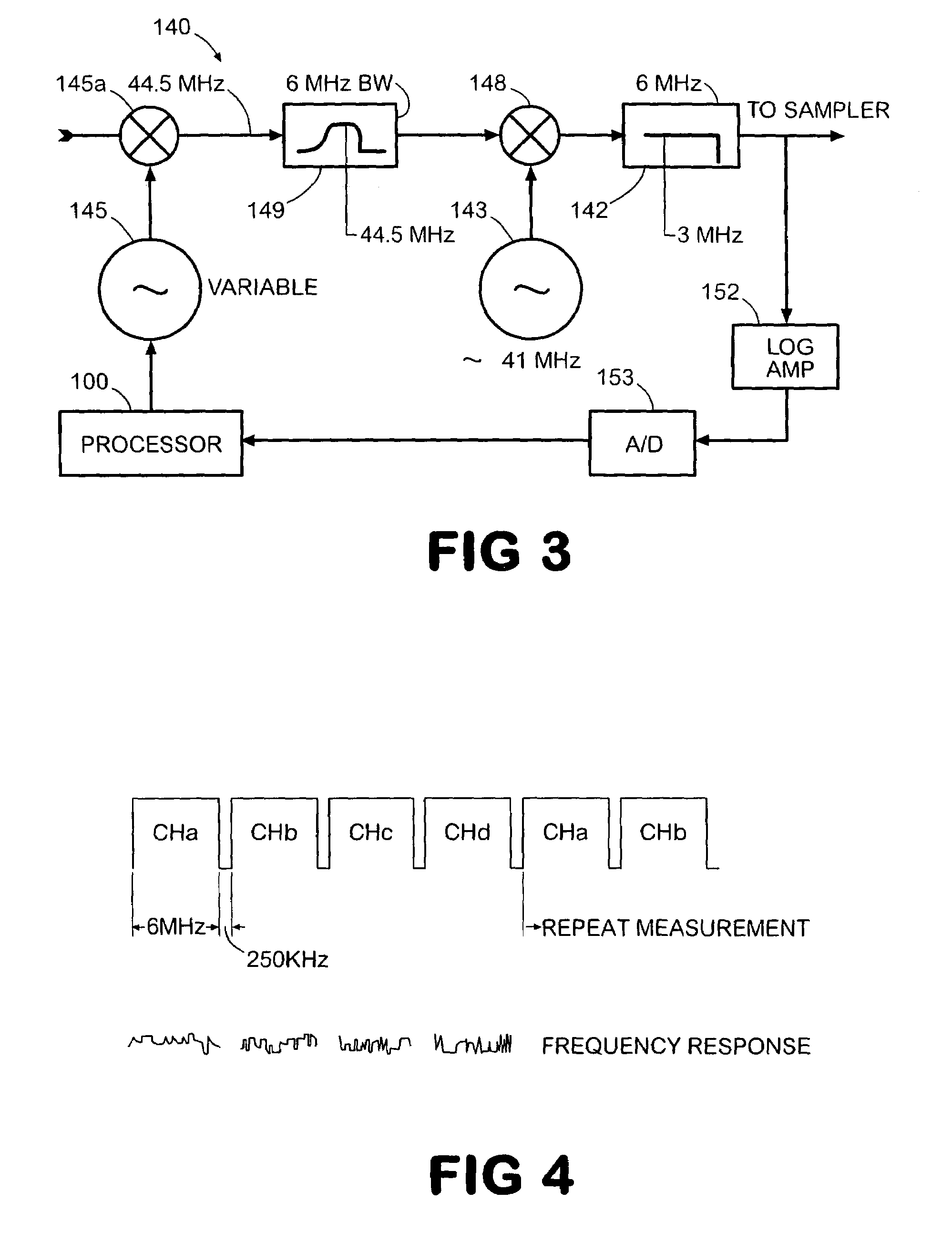
[0024]The frequency response measurement device 10 includes a tuning circuit 22 connected to the distribution network 16 via one of the splitters 18, a measurement circuit 24 connected to the output of the tuning circuit 22, and in the preferred embodiment described herein, a display 26 for displaying the results output by the measurement circuit 24. The tuning circuit 22 is operable to tune to any of a plurality of digital channels, and may su...


PUM


Abstract

An apparatus, system, and method, for determining the total frequency response of a communication system, include one or more testers each having a tuner, digital demodulation circuitry, and a controller that measures an absolute power level at the tester location for a particular channel and that measures a relative frequency response for the channel based on the tap weight coefficients from the digital demodulation circuitry. The absolute and relative measurements are combined and then recorded by each tester. The combined values of two or more testers are compared to determine the total frequency response of the communication system. The relative response measurements are converted from time domain to frequency domain by fast Fourier transformation. The controllers maintain a channel plan for sequencing the sweeping of consecutive channels.

Description

FIELD OF THE INVENTION[0001]The invention relates to a method, system, and apparatus for providing a high resolution, non-intrusive determination of frequency response for a cable television (CATV) network carrying one or more digital channels.BACKGROUND OF THE INVENTION[0002]Digital television signal broadcasting has several advantages over traditional analog television signal broadcasting. A digital data channel, as with an analog channel, is susceptible to noise, but so long as the received signal overcomes a threshold signal-to-noise level, the transmission is essentially error-free. Channel distortion and noise can be corrected in a digital system by using adaptive equalizers, as well as various error correction and error tolerance methods. Employing coding techniques overcomes channel-related signal impairments and optimizes bandwidth efficiency. Therefore, digital television signals are less susceptible to image distortion and interference. As a result, digital television sig...

Claims


Application Information

Patent Timeline
Patent Type & Authority Patents(United States)
IPC IPC(8): H04B3/46
CPCH04B3/46
Inventor CHAPPELL, DANIEL K.
Owner VIAVI SOLUTIONS INC
Why Eureka
Try Eureka