Device for surface stimulation of acupuncture points

a surface stimulation and acupuncture technology, applied in the field of devices for stimulating acupuncture points, can solve problems such as and achieve the effect of lowering the power requirements of devices

Inactive Publication Date: 2005-11-01
THE RUSSELL GRP
View PDF15 Cites 88 Cited by
  • Summary
  • Abstract
  • Description
  • Claims
  • Application Information

AI Technical Summary

Benefits of technology

[0089]My device provides a non-invasive means for stimulating a selected acupuncture point. It can be used to stimulate almost any acupuncture points. Through use of its novel electrode configuration, electrical impulses are delivered to the selected acupuncture point with limited current loss, thus lowering the power requirements of the device. The electrode configuration also provides fo...

Problems solved by technology

Through use of its novel electrode configuration, electrical impulses are delivered to the sele...

Method used


Image

  • Device for surface stimulation of acupuncture points
  • Device for surface stimulation of acupuncture points
  • Device for surface stimulation of acupuncture points

Examples


first embodiment

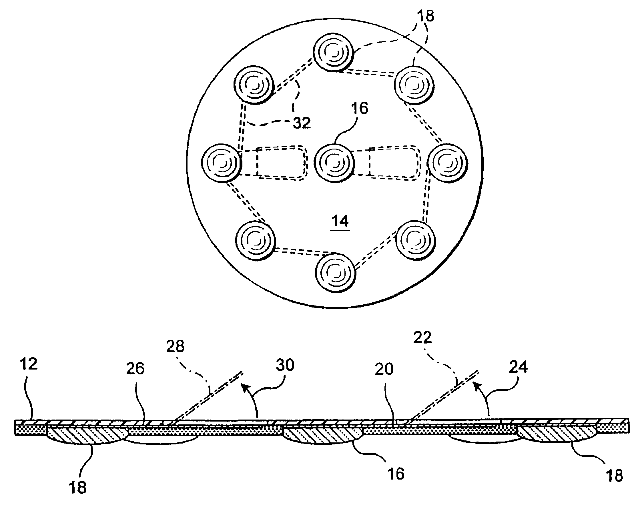
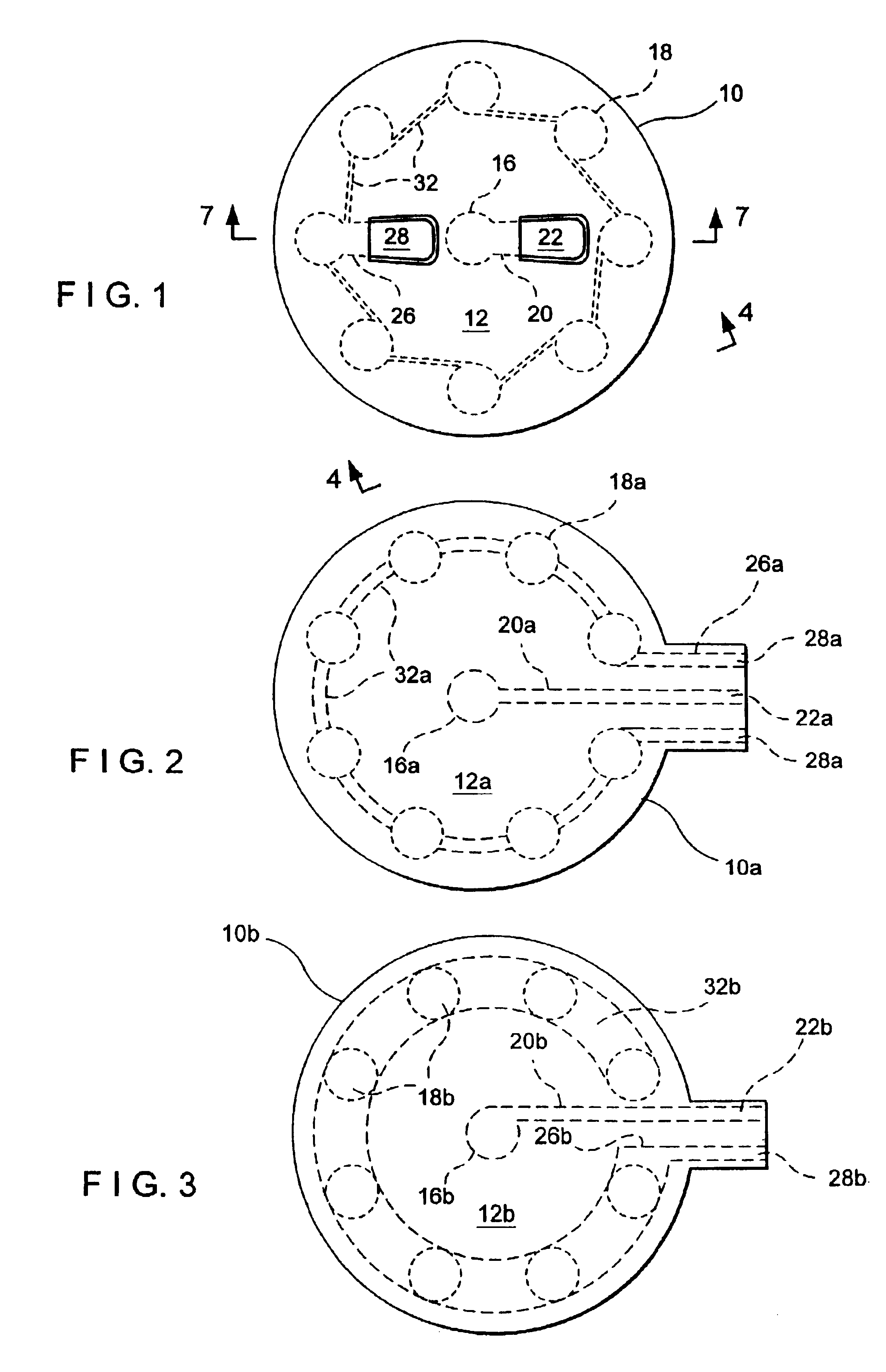
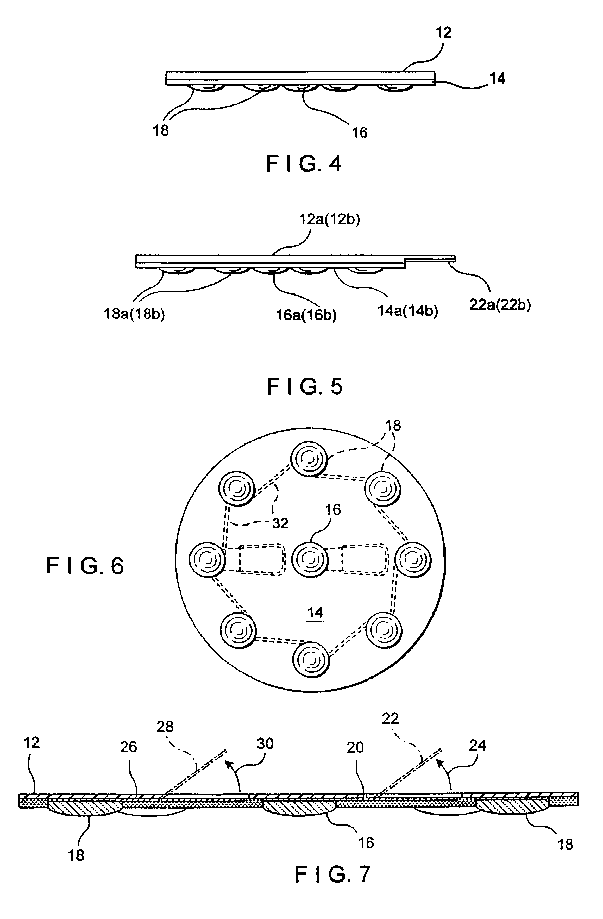
[0149]In the first embodiment, the conductor 32 extends diagonally from a radially inward portion of one gel filled hole 18 to a radially outward portion of a successive gel filled hole 18 about the circular spacing there between and over each gel filled hole. This diagonal arrangement between the gel filled holes and the circular arrangement of the gel filled holes define at about longitudinal centers of the gel filled holes 18 an effective circle that is an integral multiple (including of 1) of an average cun radially from the central gel filled hole 16. In this way, the device provides a visual cun-measuring tool for positioning it in cun dimensions relative to an acupuncture point.

second embodiment

[0150]In the second embodiment, the conductor 32a extends from the one end of the conductor 26a connected to one gel filled holes 18a across and over each of the gel filled holes 18a to an opposite end on the tab of the polyester layer. Since the resulting circle of the conductor 32a is narrower than the diameters of the holes, a cun-indicating circle from the central gel filled hole is clearly defined and since both opposite sides of the tab of the polyester layer effectively have a tab end 28a of the conductor, the device is adapted for right- or left-handed electrical connection to the circle of gel filled holes with the central hole being visually conspicuously connected to a tab end 22a in the middle. Therefore, the tab ends 22a, 28a cannot be confused if, for example, relative positive and negative connections thereto are desired.

third embodiment

[0151]In the third embodiment, the circle of the conductor 32b is wide enough to cover the gel filled holes. Circumferential alignment between portions of the conductor and the gel filled holes is, therefore, not needed. Also, only the tab end 28b of the connected conductor 26b extends onto the tab of the polyester layer.

[0152]When the device is adhered on a patient's skin over an acupuncture point, the tabs 22, 28 of the first embodiment can be raised from the layer-parallel shipping condition to a projecting, use condition that is vertical (perpendicular to the disc) as shown in FIG. 8 but could be at other projecting use angles in other embodiments (not shown), as suggested in FIG. 7. In the use condition, the tabs can be engaged by electric supply clamps 34 and wire leads of a known stimulator (not shown) to provide electric pulses for a pulsed electric field 36 as shown in FIG. 8 that stimulates an acupuncture point in the electric-field-penetrated patient's body (not shown) be...


PUM


Abstract

A device, which is preferably disc shaped, has two primary layers. A first layer has one side, which is the lower side in use, for adhering to a patient's skin surface, a second, upper layer on the underside of which electrical circuitry is printed or affixed so that the electrical circuitry is sandwiched between the layers. The device can be made in several sizes to accommodate patient size and location of the acupuncture point to be stimulated. Two distinct forms of the device are presented: a single use and a reusable device for. In the single use device, the first, lower layer is preferably a foam with non-conductive adhesive on both sides: the bottom side for adhering to the skin and the top side for adhering to the upper polyester disc. The holes through this lower foam layer include, preferably, eight holes spaced concentrically about one central hole in the middle of the lower foam layer. All these holes are, preferably, overfilled with an electrically conductive gel that projects from the lower foam layer. The conductive circuitry preferably printed on the underside of the upper layer provides a series connection to the gel in each of the eight concentric holes and a separate connection to the gel in the center hole when the upper layer is adhered to the lower layer. The printed circuitry may be a silver/silver chloride polymer film, also provides for a tab(s) which can be permanently or temporarily affixed to an integral or remote simulator through direct contact or wire leads. In the reusable device a pressure-sensitive adhesive material forms the lower layer which allows for multiple applications to a patient's skin. The adhesive lower layer is transparent to show the circular central electrode the annular electrode. The electrodes are preferably silver/silver chloride polymer film. In either configuration, metal core insulated leads can be use for electrical connection with the opposite ends of the leads connected to jacks for connection to an impulse stimulator or can end in electrically conductive tabs.

Description

CROSS REFERENCE TO RELATED APPLICATION[0001]This application is a continuation-in-part of co-pending International application PCT / US02 / 08480 filed Mar. 19, 2002, which designated the U.S., claims the benefit of U.S. Provisional Patent application No. 60 / 277,367 filed in English Mar. 20, 2001, and incorporates the same by reference.BACKGROUND OF THE INVENTION[0002]The invention relates to a device for stimulating acupuncture points of a body and, more particularly, for stimulating them from the surface of the body with electricity.[0003]Acupuncture is an ancient medical art dating back more than 2000 years. Traditionally, points in the human body (herein called acupuncture points) were reached by piercing the body with fine wires or needles. The needles were then rotated or oscillated about their longitudinal axes, for example by rubbing an exposed end of a needle between a thumb and finger, to stimulate the acupuncture points.[0004]Stimulation of specific acupuncture points has bee...

Claims


Application Information

Patent Timeline
IPC IPC(8): A61N1/32A61N1/04A61H39/00A61N1/34
CPCA61H39/002A61N1/0408A61N1/0476A61N1/0492A61N1/32A61N1/36021A61N1/0428A61N1/0456
Inventor GILBERT, BRUCE R.
Owner THE RUSSELL GRP
Why Eureka
Try Eureka