Energy absorbing device for ballistic body armor

a technology of energy absorption and ballistic body armor, which is applied in the field of protective vests, can solve the problems of affecting the safety of wearers, and exposing wearers' areas to subsequent rounds, so as to improve the ballistic performance of the package, improve the safety and performance of the vest, and reduce the trauma of wearers

Inactive Publication Date: 2005-11-08
SAFARILAND
View PDF31 Cites 46 Cited by
  • Summary
  • Abstract
  • Description
  • Claims
  • Application Information

AI Technical Summary

Benefits of technology

[0014]More particularly, the ballistic vest of the present invention incorporates a frame system made of low density plastic, composite or other semi-rigid materials which is attached to the ballistic package to improve safety and performance of the vest. The frame system is directly attached to the ballistic fabric material of a ballistic package in the vest. The frame system distributes energy across the surface of the ballistic package, thus reducing trauma to the wearer and also improving ballistic performance of the package. The frame system permits the production of lower cost and lighter weight ballistic vests. The frame system offers resistance to the amount of the ballistic package travel and material twist into the center of the area of impact. The frame system thereby reduces the amount of depression or backface trauma caused by stopping the projectile. Consequently, injury caused by blunt force trauma is reduced, thereby improving safety of the vest. Because the frame system reduces the amount of material travel, the amount of ballistic materials can be reduced, thereby providing an effective ballistic system which is lighter in weight and thickness, which improves wearer comfort and reduces the overall cost for manufacturing the vest. The frame structure increases the V-50 performance of current ballistic panel configurations.
[0015]Preferably the frame structure is sewn on top of or in between the multiple plies of ballistic fabric contained within a ballistics package. The frame supports the ballistic fabrics and acts to distribute energy in a ballistic event. The frame structure is cut in a geometric form with open areas dispersed throughout the frame structure. The exact size, shape and thickness of the open areas will vary based upon the size of the ballistics panel or other factors related to each ballistic fabric or type of projectile that the ballistic vest is designed to stop. The multiple plies of ballistic material to which the frame structure is attached can consist of woven or non-woven Kevlar, Spectra, Nylon or Zylon fibers, or other known ballistic materials. Typically, the frame structure is positioned on the strike face side of the vest with not more than 50% of the ballistic fabric plies in front of the frame structure. Because the frame is semi-rigid, it prevents the ballistic package from sagging and allows the vest to be worn in a loose condition, thereby reducing heat build-up and improving wearer comfort.
[0016]In a ballistic event, the projectile strikes the ballistic materials and energy is transferred to the frame structure via the fibers in the ballistic fabrics. When the bullet contacts the surface, it expands, twists and becomes entangled in the fibers, and tension is put on the fibers stretched between the frame structure of the ballistic vest. As the fabric bunches around the bullet, the frame structure is loaded. The frame structure being flexible offers resistance to the amount of the ballistic material travel and twist into the center area of impact. The frame structure thereby reduces the amount of depression of backface trauma caused by the slowing projectile. The frame structure, by supporting the ballistic fabric, reduces the chance of the panel bunching or moving after a ballistic event.

Problems solved by technology

A vest must not be too flexible where is cannot protect the wearer.
A problem associated with currently available concealable soft body armor ballistic vests is that when the vest is shot the ballistic package can twist or ball up potentially exposing areas of the wearer to subsequent rounds.
Another continuing problem of existing concealable ballistic vests is that when worn for prolonged periods of time the wearer becomes overheated or because of the flexibility of the ballistic material, the ballistic package can sag forming set wrinkles in the bottom of the carrier.

Method used


Image

  • Energy absorbing device for ballistic body armor
  • Energy absorbing device for ballistic body armor
  • Energy absorbing device for ballistic body armor

Examples


Embodiment Construction

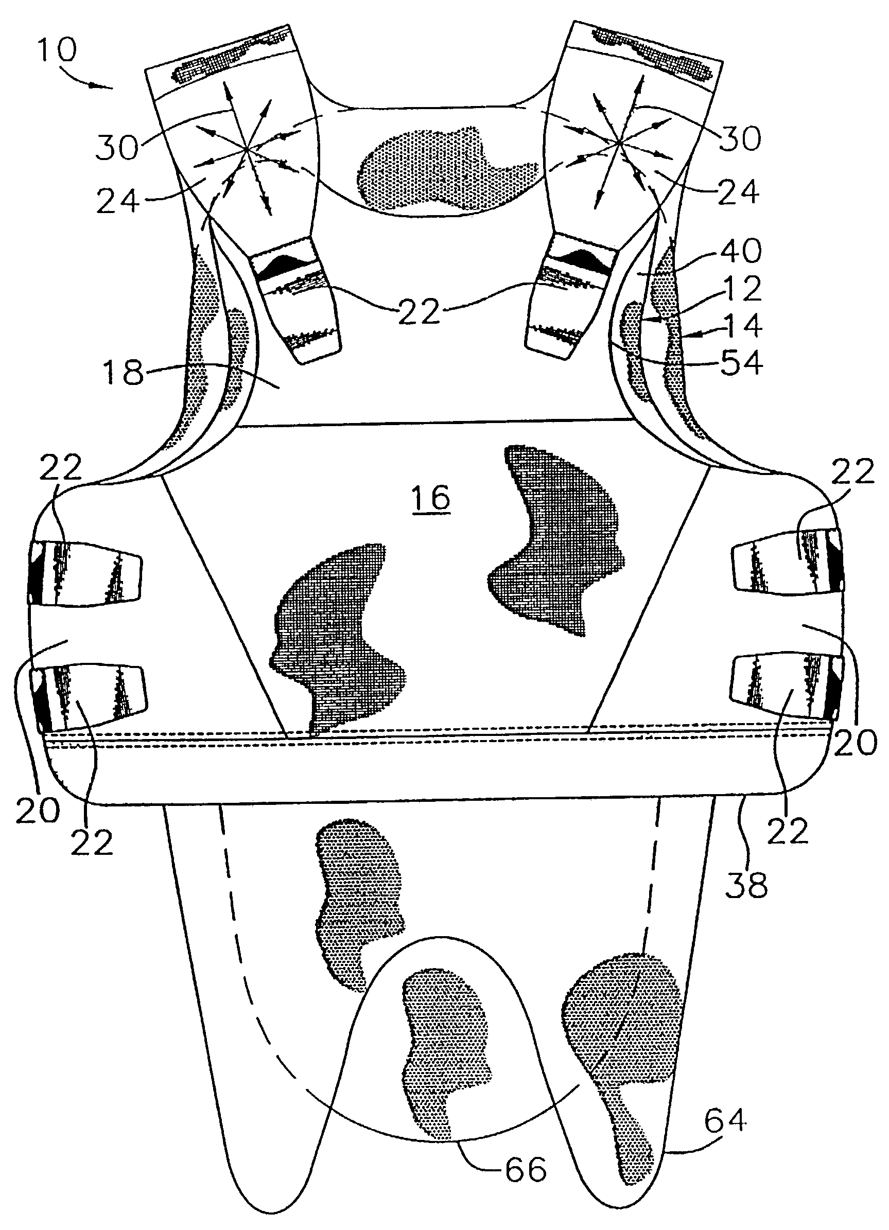
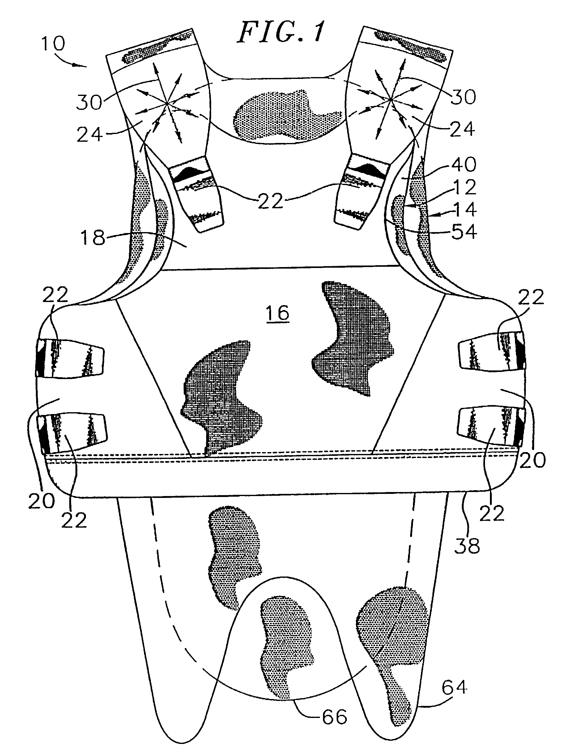
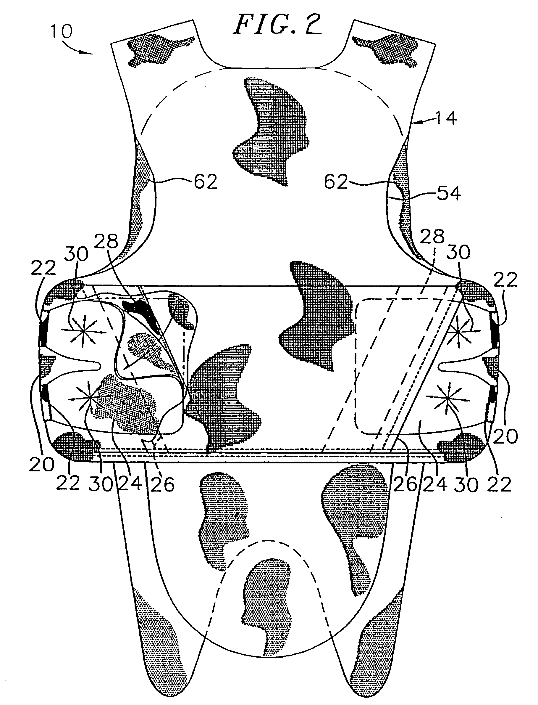
[0024]A ballistic vest 10 of the present invention is shown in FIGS. 1 and 2. The ballistic vest 10 is a concealable vest of the soft body armor type commonly worn by law enforcement officers. The ballistic vest includes a front panel 12 and a rear panel 14. The front panel 12 protects the chest and stomach of the wearer while the rear panel 14 protects the back of the wearer. Both the front and rear panels protect the sides of the wearer as will be discussed in more detail below.

[0025]The front panel 12 may include a trapezoidal center panel 16 and hook compatible fabric located along the top 18 and sides 20 of the front panel 12. Top 18 and sides 20 provide a large area for hook fasteners 22 to secure the front panel and rear panel together around the wearer. Top 18 and sides 20 allow for placement of fasteners 22 at any location to provide an optimal fit for the particular wearer. Neoprene composite straps 24 located at the top and sides of the ballistic vest are attached to the ...


PUM


Abstract

A ballistic vest having a front panel and a rear panel attached to each other by releasable connectors. The front and rear panel each have a ballistic package having a plurality of sheets of ballistic material and a semi-rigid frame structure attached to the layers of the ballistic material. The frame structure has a plurality of members defining openings in the frame structure wherein the frame structure absorbs energy from a projectile entering the sheets of ballistic material.

Description

CROSS-REFERENCE TO RELATED APPLICATION(S)[0001]This application claims priority from U.S. Provisional Application No. 60 / 462,890, filed Apr. 15, 2003.FIELD OF THE INVENTION[0002]This invention relates to protective vests, and more particularly, to body armor commonly known as a ballistic vest, which incorporates a semi-rigid frame structure attached to the ballistic package.BACKGROUND OF THE INVENTION[0003]Ballistic vests have saved the lives of many law enforcement officers in recent years. As a result, law enforcement agencies have made it mandatory for their officers to wear a ballistic vest while on duty.[0004]Ballistic vests have been available in recent years as a protective panel having overlying layers of a fabric made from woven high tensile strength fibers. Woven fabrics from an aramid fiber known as Kevlar, for example, have been used successfully in ballistic vests because of the high energy absorption properties of the fabric material. The material is also reasonably li...

Claims


Application Information

Patent Timeline
Patent Type & Authority Patents(United States)
IPC IPC(8): F41H1/00F41H5/04F41H1/02F41H5/00
CPCF41H5/0492F41H1/02
Inventor CARLSON, RICHARD A.
Owner SAFARILAND
Why Eureka
Try Eureka