Cable slack and guide monitoring apparatus and method for a lift device

a monitoring apparatus and lift device technology, applied in the direction of hoisting equipment, thin material handling, web handling, etc., can solve the problems of workers accidentally hitting loads, system is not suited to maneuvering objects of various weights, and the balancer is not easily changed, so as to facilitate improved performance and improve the performance and safety of intelligent lifting devices

Inactive Publication Date: 2005-08-18
GORBEL INC
View PDF23 Cites 29 Cited by
  • Summary
  • Abstract
  • Description
  • Claims
  • Application Information

AI Technical Summary

Benefits of technology

[0018] The technique described herein is advantageous because it is simple and can be adapted to any of a number of lift devices employing a cable and lift pulley on which the lift cable or line is wound. In addition, it can be used to in the automated control and customized setup of a lift to facilitate improved performance. As a result of the invention, the performance and safety of intelligent lifting devices is improved. One of the most important properties of the invention is that the actuator and pulley operate under the control of the operator on the end-effector so as to follow the operator's hand motion upwardly and downwardly—yet the line does not become slack if the end-effector is physically constrained from moving downwardly while the end-effector is pushed downwardly by the operator.

Problems solved by technology

The fixed preset forces of balancers are not easily changed in real time, and therefore these types of systems are not suited for maneuvering of objects of various weights.
A problem may occur when the operator presses downward on the end-effector to engage the load with a gripping mechanism such as suction cups; the controller and actuator interpret this motion as an attempt to lower the load.
Also, during fast maneuvers workers can accidentally hit the loads they intend to lift or their surrounding environment (e.g. conveyor belts) with the bottom of the end-effector.
These occurrences may cause slack in the line since the operator might push downward on the end-effector handle to locate box, while the end-effector is constrained from moving downward.
As a result, the actuator causes the pulley to release more line than necessary, thereby creating “slack” in the cable.
Once slack is produced in the line, by this or other circumstances, when the operator pushes upward on the handle, the slack line can become entangled around the operator's neck, arms or hands, or interfere with other equipment, creating the possibility for injury or damage.
A slack cable is also a problem for the overall mechanics of the lift.
Repeated occurrences of slack will eventually cause the cable to come off the drum or become entangled in other components or hardware in the actuator.
Covers that go over the drum are not sufficient to prevent the cable from eventually becoming entangled in the mechanics of the actuator.
Slack can occur even when other end effectors are used for load gripping means.

Method used


Image

  • Cable slack and guide monitoring apparatus and method for a lift device
  • Cable slack and guide monitoring apparatus and method for a lift device
  • Cable slack and guide monitoring apparatus and method for a lift device

Examples


Embodiment Construction

[0023] For a general understanding of the present invention, reference is made to the drawings. In the drawings, like reference numerals have been used throughout to designate identical elements.

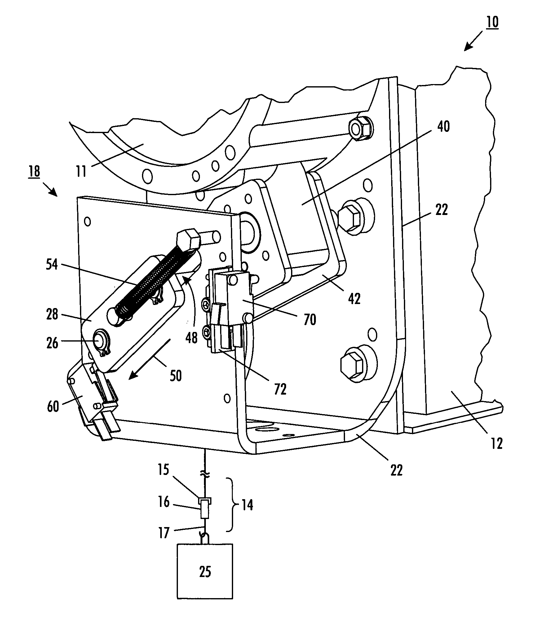
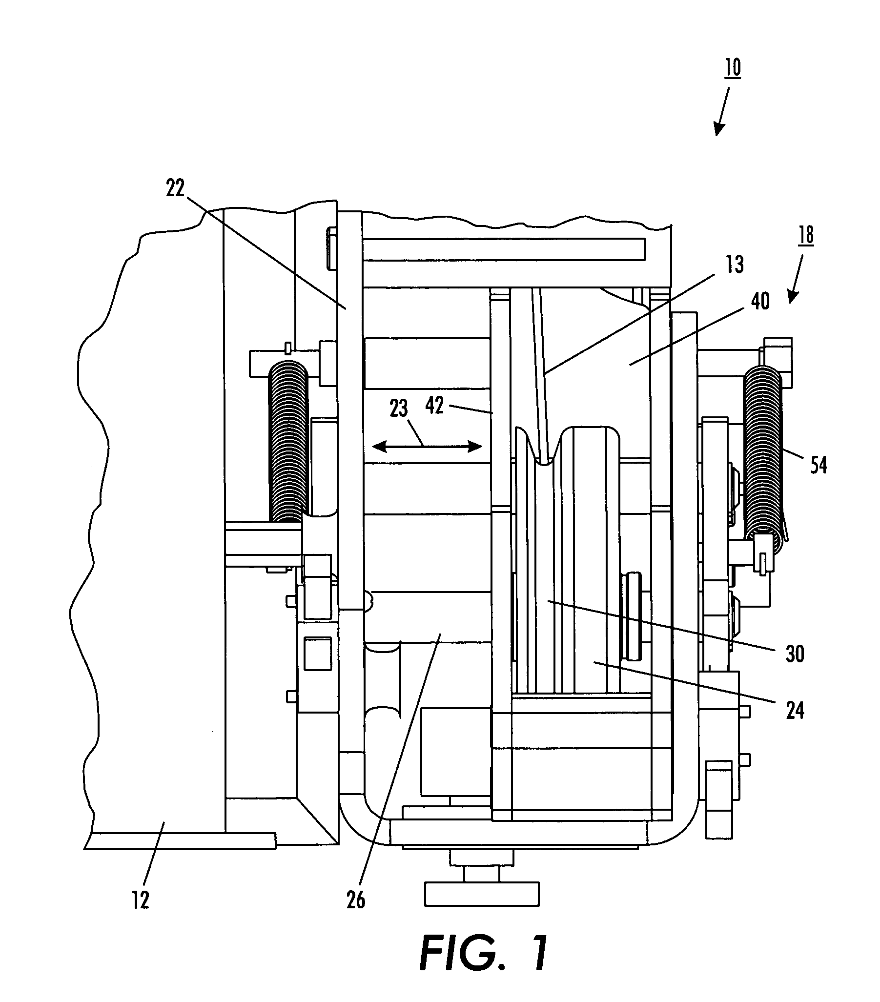
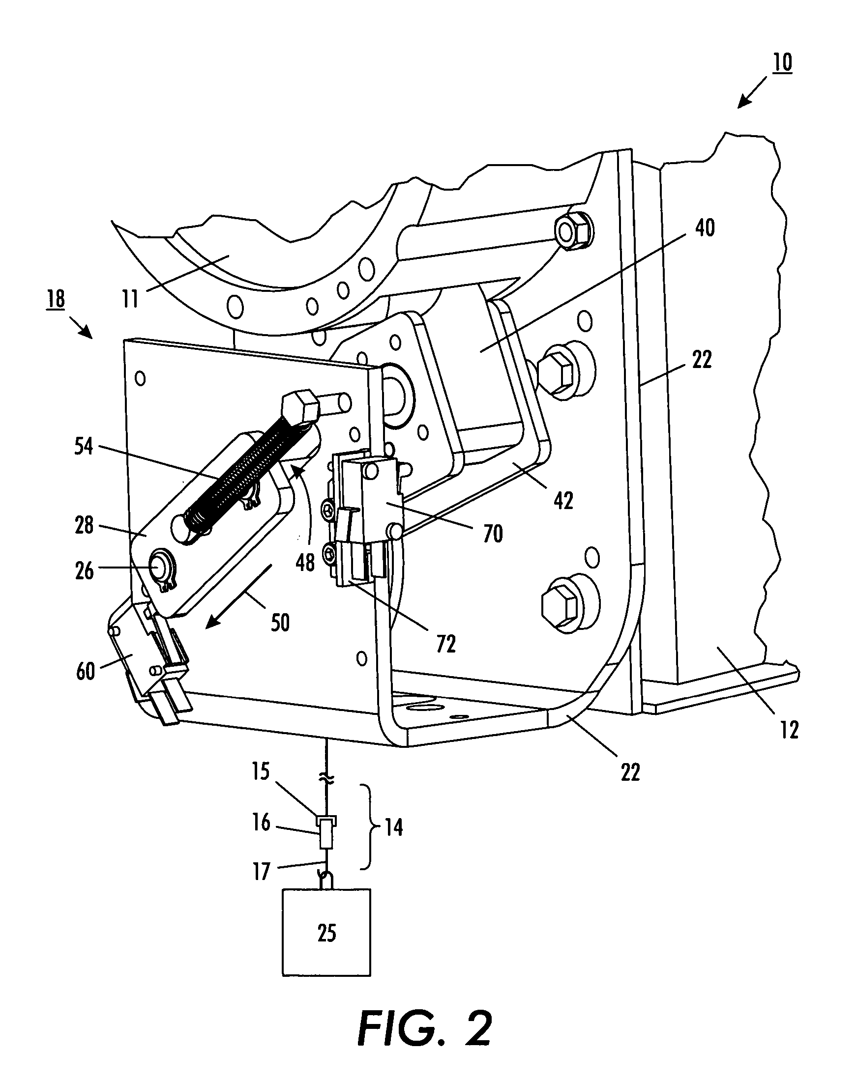
[0024] Referring to FIGS. 1 and 2, there is depicted an embodiment of the invention, showing a take-up or drive pulley and associated mechanical assemblies in an exemplary human power amplifier 10. At the top of the device, a take-up pulley 11, driven by an actuator 12, is attached directly to a ceiling, wall, or overhead crane (not shown). Encircling pulley 11 is a line 13. Line 13 is capable of lifting or lowering a load 25 when the pulley 11 turns. Line 13 can be any type of line, wire, cable, belt, rope, wire line, cord, twine, string or other member that can be wound around a pulley and can provide a lifting force to a load. Attached to line 13 is an end-effector 14, that includes a human interface subsystem 15 (including a handle 16) and a load interface subsystem 17, which in this em...


PUM


Abstract

The present invention is a method and apparatus for monitoring the condition of a cable in a human power amplifying lift system. The method and apparatus employ a cable slack sensor and a cable end sensor to override and prevent the lift from continuing to unwind the lift cable when slack or and end of travel limit has been reached.

Description

[0001] This invention relates generally to an intelligent material handling devices that lift and lower loads as a function of operator-applied force, and more particularly to an apparatus and method to improve the safety and performance for such devices by monitoring the cable tension and cable winding on a lift pulley so as to prevent slack in the cable. BACKGROUND AND SUMMARY OF THE INVENTION [0002] The present invention is directed to intelligent material handling devices that lift and lower loads as a function of operator-applied force. The devices described herein are different from manual material handling devices currently used by assembly and warehouse workers in that the devices respond to the operator's interaction with the lifting device, and not merely to an operator's pushing, depressing or squeezing of a switch or button on a control pendant. [0003] More specifically, the present invention is directed to a class of material handling devices called balancers or lifts, ...

Claims


Application Information

Patent Timeline
Patent Type & Authority Applications(United States)
IPC IPC(8): B66D1/48B66D3/18
CPCB66D3/18B66D1/485
Inventor TAYLOR, MICHAEL K.SCHOLAND, MARK F.
Owner GORBEL INC
Why Eureka
Try Eureka