Tooling for rivet gun

a tooling and rivet gun technology, applied in the field of rivet gun tooling, can solve the problem of reducing the possibility of non-shear condition, and achieve the effect of maximum strength connection

Inactive Publication Date: 2005-11-08
TEXTRON INNOVATIONS
View PDF13 Cites 6 Cited by
  • Summary
  • Abstract
  • Description
  • Claims
  • Application Information

AI Technical Summary

Benefits of technology

[0013]Another object of the present invention is to provide a riveting technique which leaves the exterior aircraft surface smooth with no deformation of the skin and the rivets not visible.
[0014]Another object of the present invention is to provide a back riveting gun which precisely upsets all of the rivets so as to provide a maximum strength connection.

Problems solved by technology

Since the single stroke of the rivet gun is carefully limited by a stop, it upsets the shank of the rivet the precise amount necessary to swell the shank and upset the end of the shank to form a head and tightly contain the two or more sheets being joined.
The spring compression that is generated clamps both the sheets being riveted together and reduces the possibility of a non-shear condition existing between the sheets.

Method used


Image

  • Tooling for rivet gun
  • Tooling for rivet gun
  • Tooling for rivet gun

Examples


Embodiment Construction

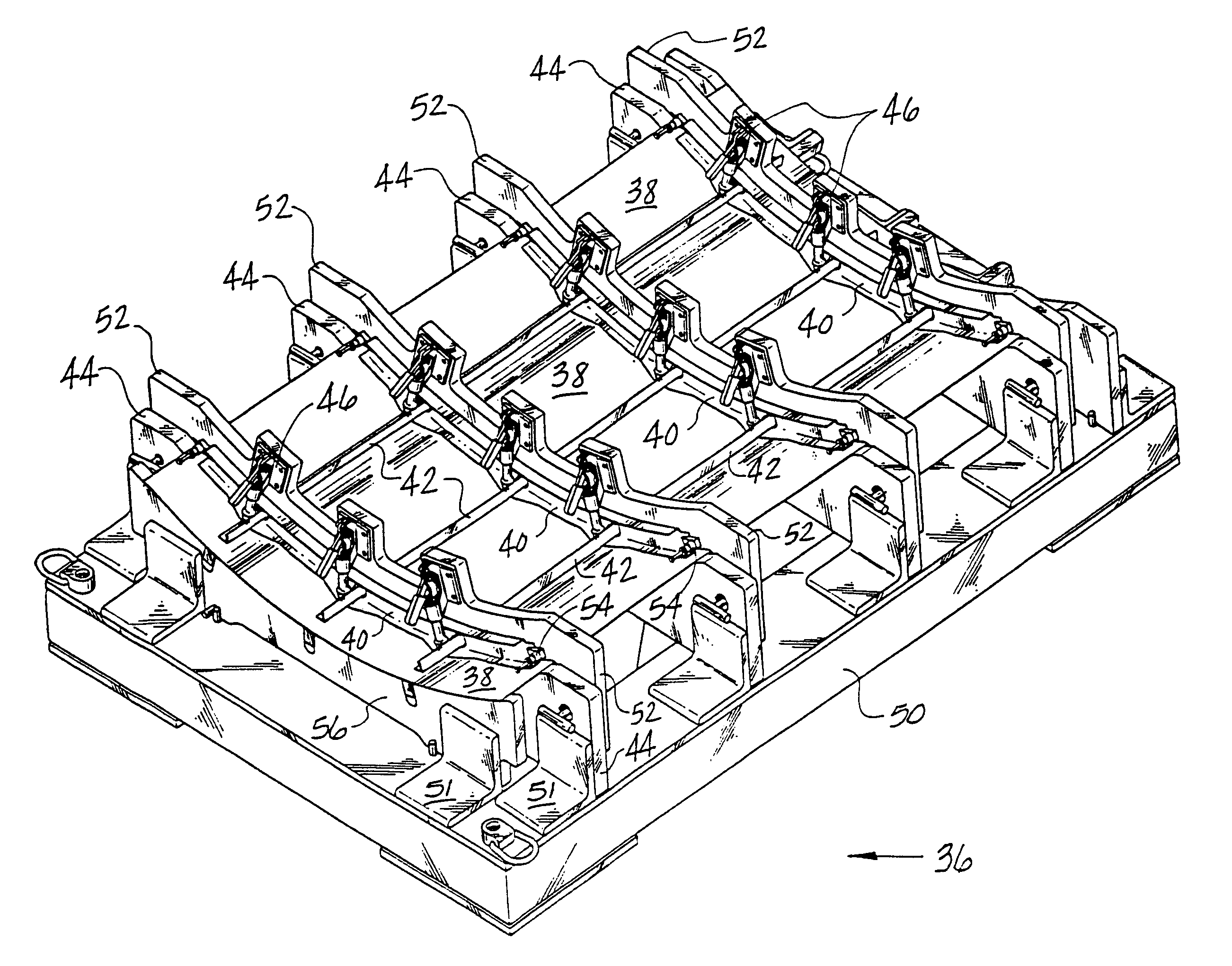
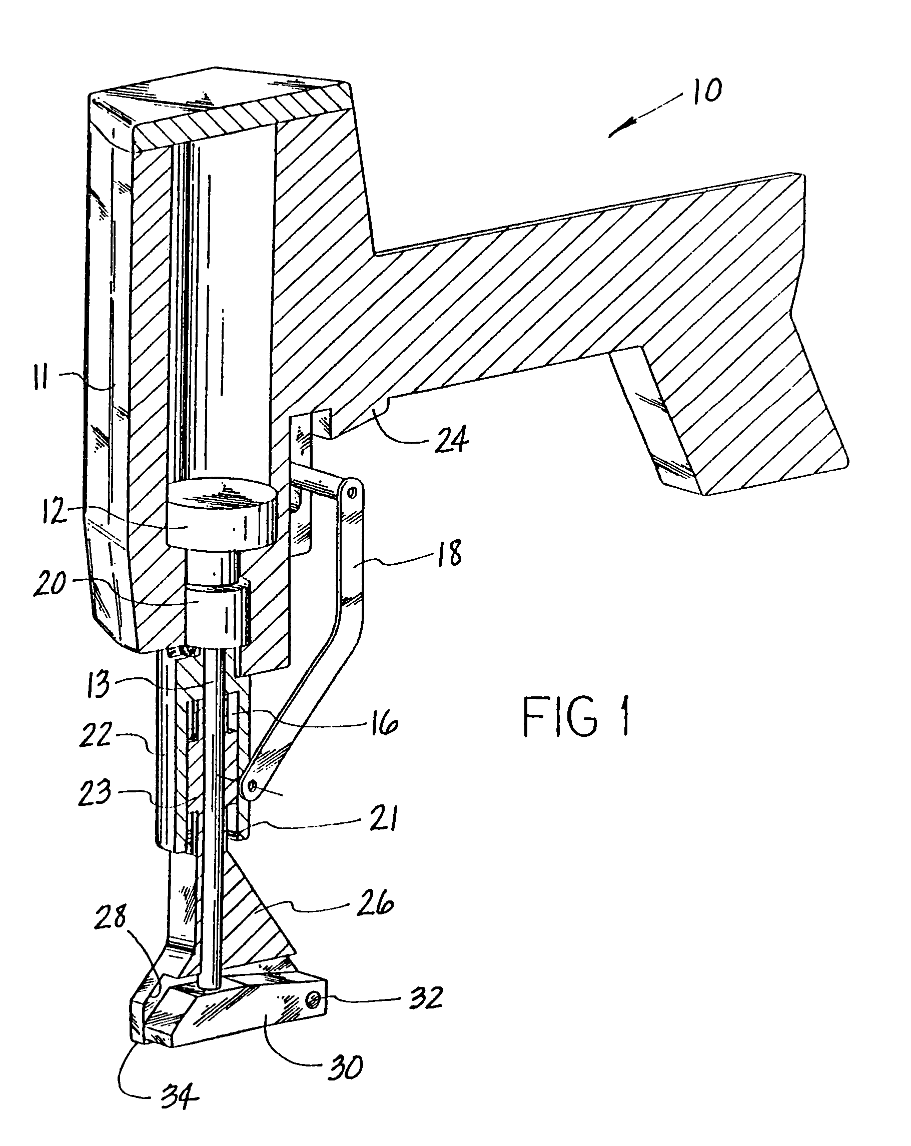
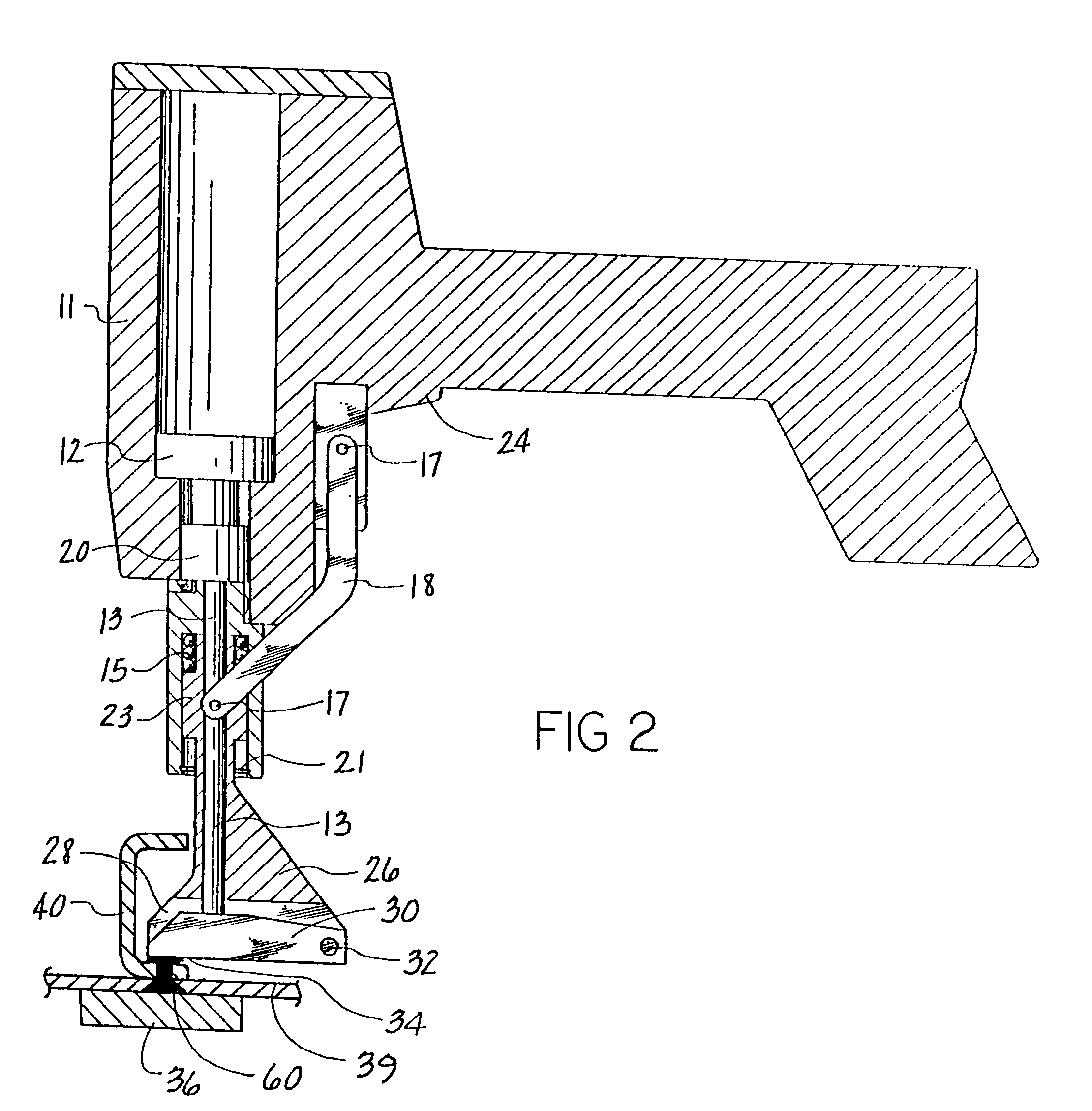
[0021]The riveting method of the present invention is accomplished through the use of riveting gun 10 shown in FIGS. 1 and 2 in conjunction with fixed tooling generally identified by numeral 36 shown in FIGS. 3 and 4.

[0022]The riveting gun 10 is a single impact gun including a housing 11 containing a piston 12 which is concentrically attached to impact pin 13, which in turn drives hammer 30 to upset a back rivet 60, as illustrated in FIG. 2. Rod and hammer guide 26 is integral with sleeve 23 and slides in sleeve 22 which is integral with housing 11. Located on the bottom of hammer guide 26 is a bearing surface 34 for engaging the surface being riveted. Located in spring chamber 16 as shown in FIG. 2 is a coiled compression spring which forces sleeve 23 along with the rod and hammer guide 26 downward against snap ring 21. In both the FIGS. 1 and 2 positions, sleeve 23 is in its fully compressed position with trigger 24 ready to fire when depressed.

[0023]The locking mechanism for the ...


PUM

PropertyMeasurementUnit
shapeaaaaaaaaaa
speedaaaaaaaaaa
forceaaaaaaaaaa

Abstract

Method and apparatus of back riveting construction for sections of aircraft structure utilizing the flush riveting wherein the back bar tooling for all the rivets in the entire section is a single piece of stationary tooling which conforms to the exterior shape of the aircraft section. The rivet gun is a single impact pneumatic gun with a rivet driving hammer which is offset from the axis of the gun's piston and impact pin to upset rivet under C-channel flanges.

Description

[0001]This application is a divisional of U.S. patent application Ser. No. 10 / 224,133, filed Aug. 20, 2002, now U.S. Pat. No. 6,820,319.[0002]The present invention relates to an apparatus and method for installing rivets in aircraft structures and more particularly to a hand-held single impact rivet gun used for back riveting in conjunction with back bar tooling.BACKGROUND OF THE INVENTION[0003]Structural joining processes used for aircraft airframe skin structure basically are either bonded or riveted. Aside from other engineering and manufacturing factors used for the selection of the appropriate joining process, bonded structure has superior aerodynamic qualities while riveted structure costs less to produce. A need for a joining process which is aerodynamically smooth and inexpensive as riveted structure has become a general goal in aircraft design. Devising a riveting process which can produce the smooth appearance of a bonded structure would satisfy both the esthetics, aerodyn...

Claims


Application Information

Patent Timeline
Patent Type & Authority Patents(United States)
IPC IPC(8): B21J15/00B21J15/18B21J15/42B21J15/06
CPCB21J15/02B21J15/105B21J15/14B21J15/142B21J15/18B21J15/42Y10T29/49956Y10S269/909Y10T29/53961Y10T29/49943Y10T29/49622Y10T29/5377
Inventor HECK, JOEL J.PALMER, MARK W.LONG, EARL V.GONZALEZ, RICHARD
Owner TEXTRON INNOVATIONS
Why Eureka
Try Eureka