
Sickle knife with double overlapping out of phase sickles

a technology of phase sickles and sickles, which is applied in the field of sickle knives with double overlapping out of phase sickles, can solve the problems of not being effectively cut and interfering with the efficiency of cutting action, and achieve the effect of improving cutting action and ground speed

Active Publication Date: 2005-11-08
MACDON INDS
View PDF8 Cites 66 Cited by
  • Summary
  • Abstract
  • Description
  • Claims
  • Application Information

AI Technical Summary

Benefits of technology

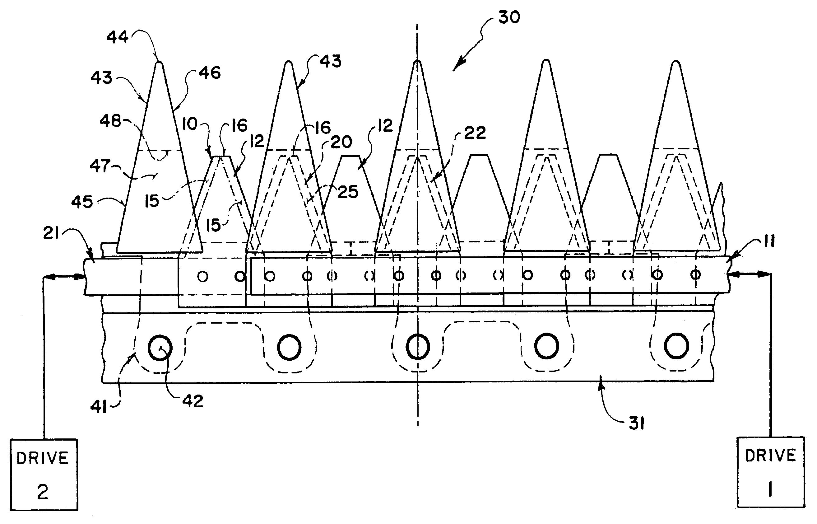
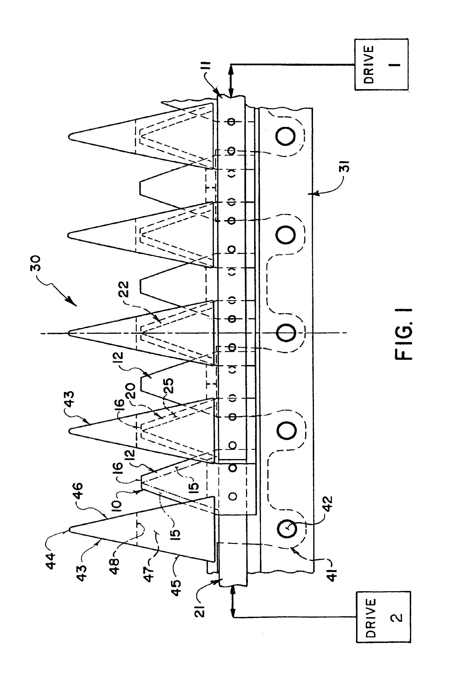
The invention is a sickle knife apparatus that improves cutting action at higher ground speeds. It includes a cutter bar with fixed knife guards and a first and second sickle with blades that move back and forth. The blades are sharpened and positioned to cut the crop at the same time, creating a double cutting action. The two sickles provide a double cutting action, but the cutting action is preferably arranged to occur between the blades and the knife guards, rather than between the blades. The blades are sharpened or chamfered to cut against the knife guards' cutting edges. The knife guards have guide slots through which both sickles pass. The invention also includes a common slot in the knife guards through which the blades of both sickles pass. The width of the blades is preferably equal to or less than the width of the knife guards to ensure that the blades are contained within the guards. This arrangement ensures that the blades are always contained within the guards when they stop and reverse, improving the cutting action.

Problems solved by technology

If the blades are chamfered in a single direction and pinching of crop between the blades is allowed to occur, this may not be effectively cut and may jam or tear and may interfere with the efficiency of the cutting action.

Method used


Image

  • Sickle knife with double overlapping out of phase sickles
  • Sickle knife with double overlapping out of phase sickles
  • Sickle knife with double overlapping out of phase sickles

Examples


Embodiment Construction

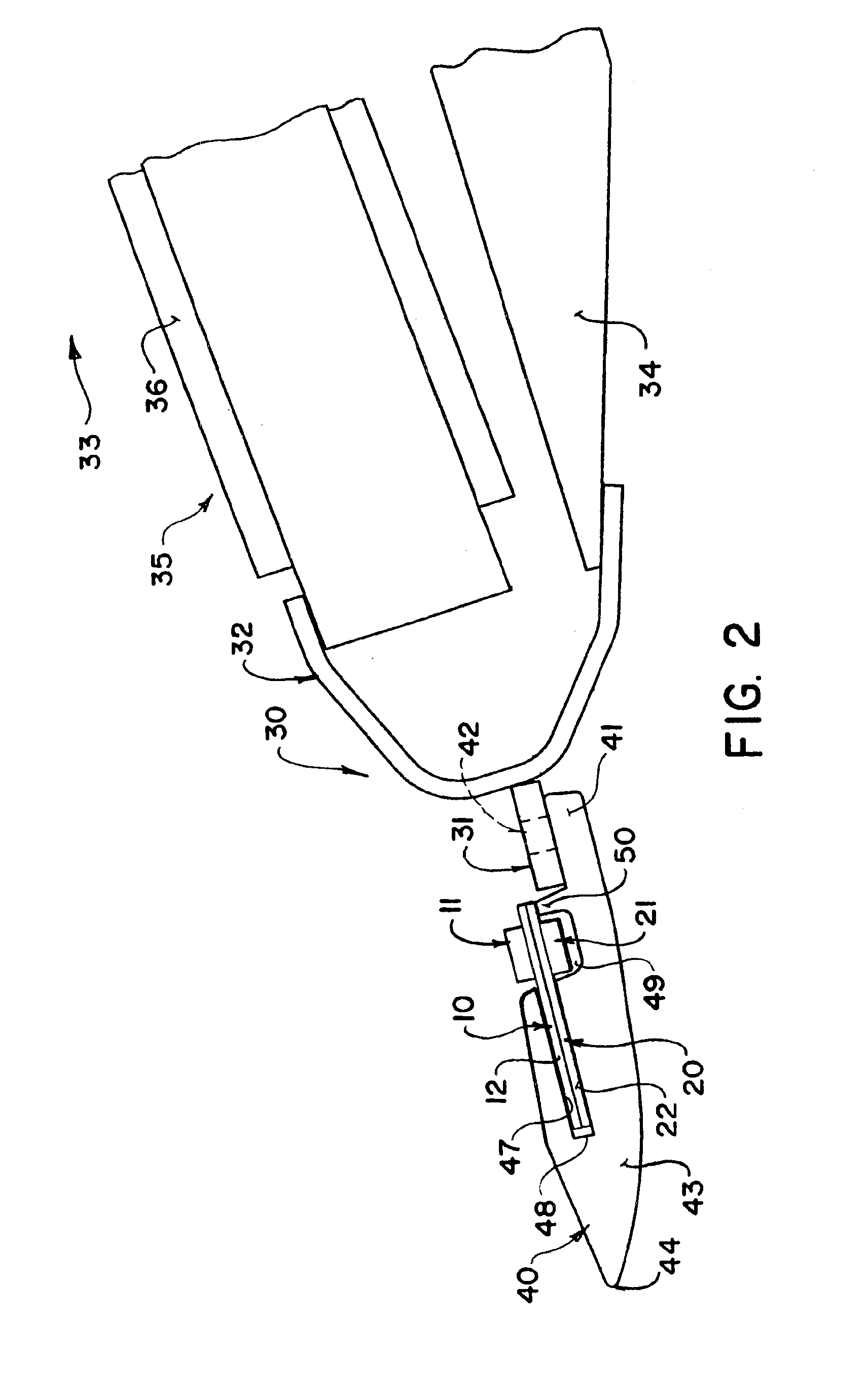
[0033]In the embodiment shown in FIGS. 1, 2 and 3, a generally conventional cutter bar and sickle knife assembly is shown and the details of this are not included since the design of the cutter bar and sickle knife can be modified in accordance with many different requirements as is well known to one skilled in the art. In general the cutter bar 30 comprises an elongate bar member 31 to which the sickle knife is attached which is carried on a structural member 32 at the forward end of a crop harvesting machine 33. In the embodiment shown the cutter bar forms part of a header having header frame members 34 and the crop transport mechanism 35 in the form of a draper 36. However again the construction and arrangement of the header itself can vary in accordance with the type of equipment with which the sickle knife is to be used.

[0034]The sickle knife assembly comprises a plurality of knife guards 40 again of a conventional construction which are formed in side-by-side pairs bolted by a...


PUM


Abstract

A sickle knife system includes two reciprocating sickles each cooperating the same fixed knife guards and each extending across the full width of the cutter bar. The guards have slots approximately twice the height of the guard of a conventional single sickle arrangement so that the two sickles can be run one on top of the other inside the guards. The width of the sickle blades at the rear edge is similar to that of the guard near the rear of its cutting edge. The blades of the top sickle are sharpened to cut against the top surface of the slot and the blades of the bottom sickle are sharpened to cut against the bottom surface of the slot. The two sickles are run out of phase, preferably about 90 degrees, so that as a result, when one sickle is near the end of its stroke within the guard where it decelerates, stops, then accelerates in the opposite direction, the other sickle is starting its cut against the side surface of the next guard.

Description

[0001]This application claims the benefit of Provisional Application No. 60 / 466,781, filed May 1, 2003.BACKGROUND OF THE INVENTION[0002]Reciprocating sickles have long been used as a cutting means for hay, grains, and many other crops. Such sickles generally comprise a series of knife guards mounted on a cutter bar and extending forwardly therefrom. The sickle bar carries a plurality of generally triangular knife blades which reciprocate back and forth across the knife guards which define two side edges causing a cutting action with the knife blades. Generally the reciprocation is arranged so that the blades move between a position aligned with one guard and a position aligned with the next causing a cutting action as they move therebetween.[0003]It is known to provide two separate sickles which overlap only in the middle so as to reduce the stresses of driving a single very long sickle. However these arrangements only operate in effect over one half of the width.[0004]It is also kn...

Claims


Application Information

Patent Timeline
Patent Type & Authority Patents(United States)
IPC IPC(8): A01D34/02A01D34/135A01D34/13
CPCA01D34/135
Inventor TALBOT, FRANCOIS R.
Owner MACDON INDS
Learn More