Torque detection device for wave gearing

a detection device and gearing technology, applied in the direction of force measurement, gearing, instruments, etc., can solve the problems of rotational ripple, insufficient linearity of detection output, and increase the manufacturing price of strain gauge type detection devices in comparison, and achieve high accuracy

Inactive Publication Date: 2005-11-08
HARMONIC DRIVE SYST IND CO LTD
View PDF16 Cites 5 Cited by
  • Summary
  • Abstract
  • Description
  • Claims
  • Application Information

AI Technical Summary

Benefits of technology

[0013]An object of the present invention is to provide an inexpensive torque detection device having strain gauges that is capable of detecting transmitted torque with high accuracy.
[0014]Another object of the present invention is to provide a torque detection device having strain gauges that is capable of detecting transmitted torque with high accuracy, and that is easily incorporated into a small-sized wave gearing.
[0021]Here, the detection segment may have a circular arc shape of 360°. Alternatively, the strain gauge pattern may include two detection segments having circular arc shapes of 180°. A configuration wherein the strain gauge pattern includes four successive detection segments having circular arc shapes of 90° is also possible. A configuration wherein the strain gauge pattern includes at least three detection segments having circular arc shapes of 45° is further possible.

Problems solved by technology

However, the linearity of the detection output is inadequate with this method, and rotational ripple components that have short periods (a multiple of the fundamental period) remain in the detection output.
The principal cause of rotational ripple is thought to be an asymmetry in the elliptical deformation of the flexible external gear.
However, the conventional torque detection devices for the wave gearings requires a large number of strain gauges that must be mounted on the flexible external gear.
This causes to increase the manufacturing price of the strain gauge type detection device in comparison with a load cell or other detection devices.
In the case of a small-sized wave gearing, it is difficult to secure enough space for mounting a large number of perpendicular biaxial strain gauges.
The wiring work for each strain gauge is also difficult.

Method used


Image

  • Torque detection device for wave gearing
  • Torque detection device for wave gearing
  • Torque detection device for wave gearing

Examples


embodiment 1

(Embodiment 1)

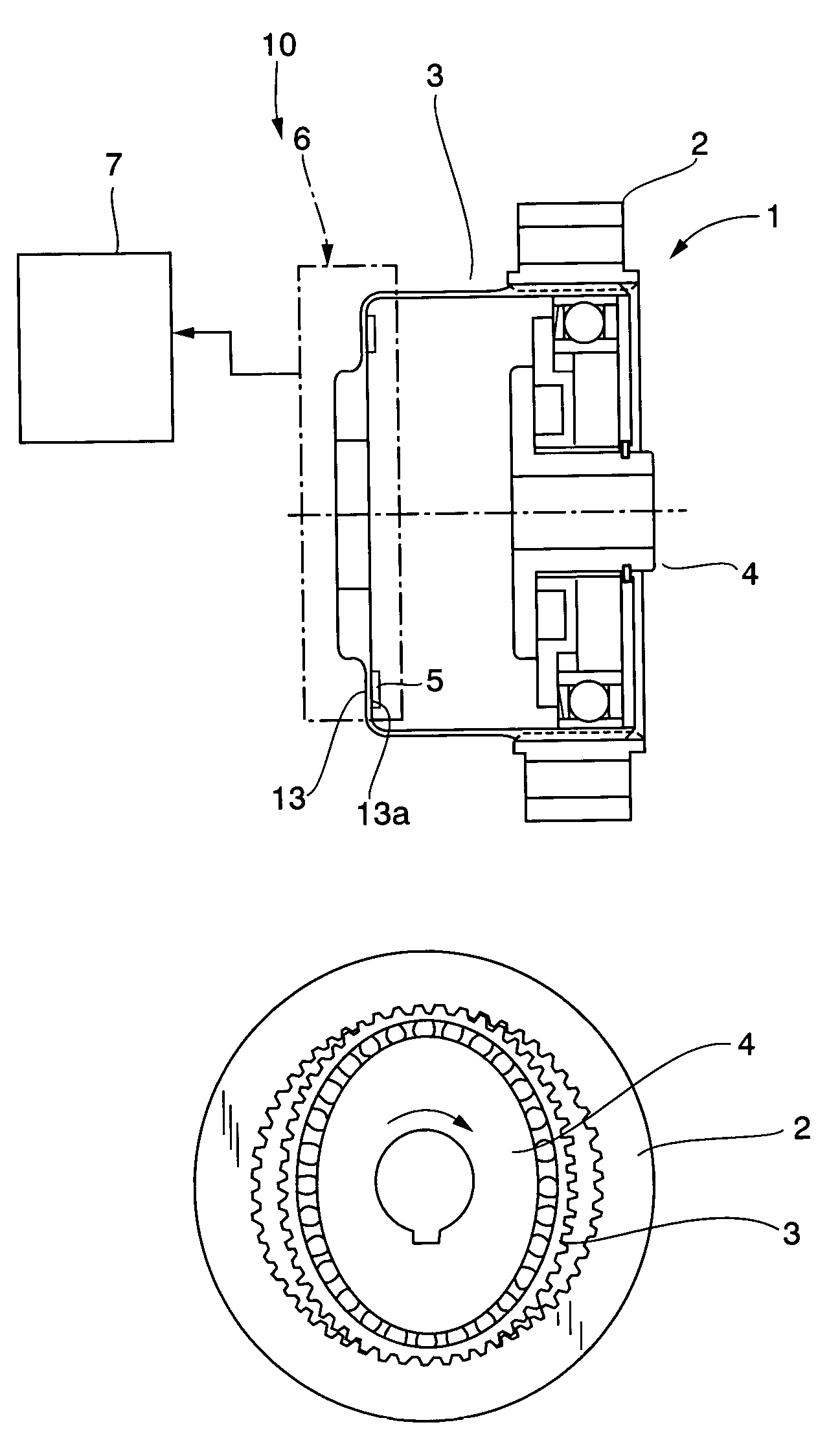
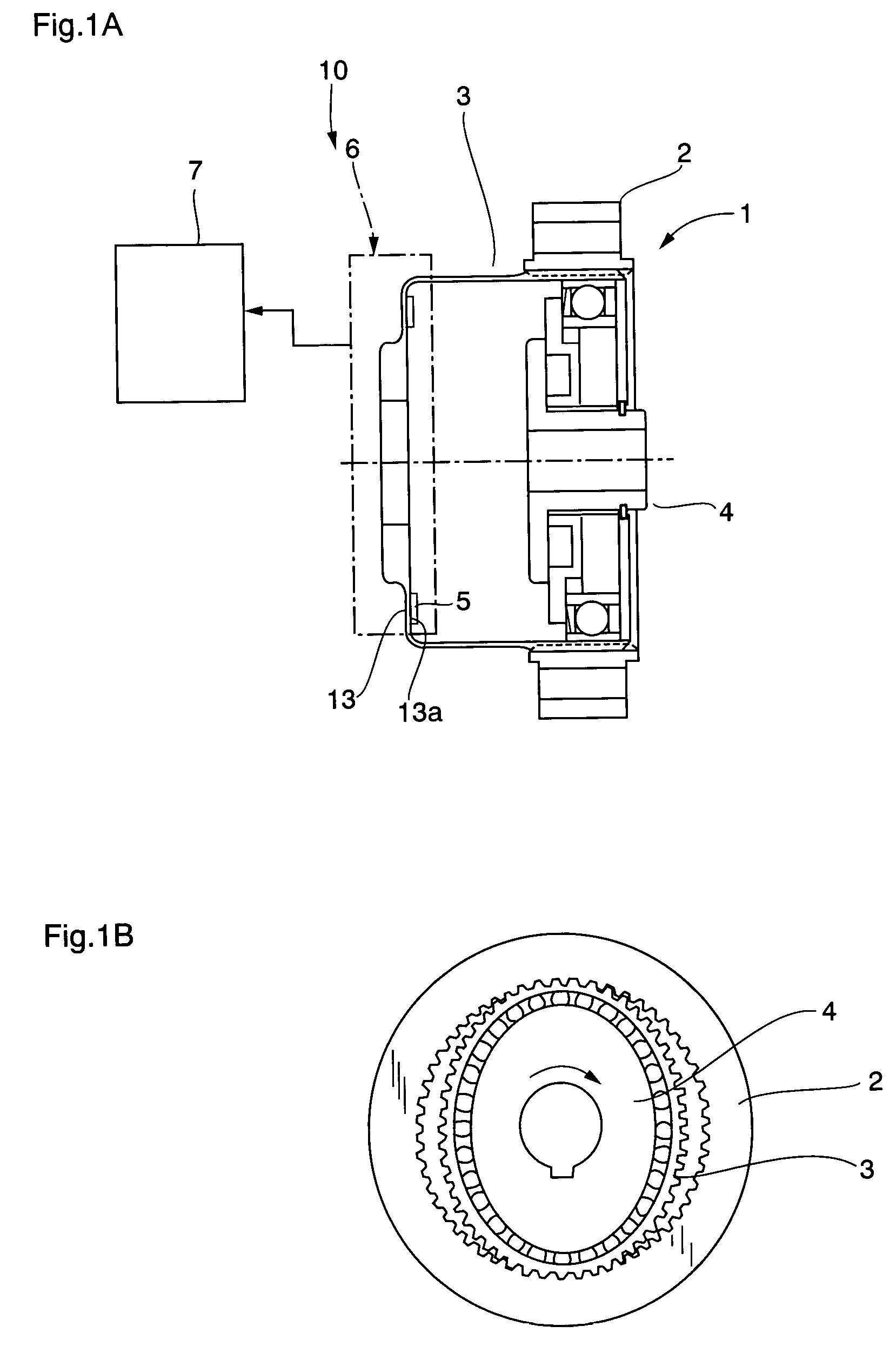
[0044]FIGS. 2A to 2F and FIGS. 3A to 3D each show examples of mounting positions in the case that uniaxial strain gauges are used as the strain gauge unit 5 mounted on the inner surface 13a of the diaphragm 13 (see FIG. 1) of the flexible external gear 3 of the wave gearing 1. FIGS. 2A and 2B correspond to FIGS. 16A and 16B. FIGS. 2C and 2D also show configurations that fundamentally correspond to FIGS. 16A and 16B, but these configurations are obtained by taking asymmetry into consideration in the sense that stretching, compression, flexing, and other types of strain along the minor and major axes in the elliptically flexing external gear 3 do not perfectly reach the same magnitude, and by adopting a reversed mounting arrangement in which the detection direction of strain gauges C and D is opposite that of strain gauges A and B. The composite signal of detected signals obtained from the bridge circuit 6 is expressed by (A+C)−(D+B) in the case of FIGS. 2A and 2B, but i...

embodiment 2

(Embodiment 2)

[0046]Although commercially available uniaxial strain gauges are used in the examples described above, it is possible to manufacture and use one or more strain gauge units having a specific strain gauge pattern. For example, in lieu of using four sets of perpendicular biaxial strain gauges such as those shown in FIG. 16A, it is possible to suggest a strain gauge unit having a strain gauge pattern in which four sets (A1, A2, B1, B2, C1, C2, D1, D2) of herringbone-shaped detection segments that correspond to perpendicular biaxial strain gauges, as shown in FIG. 4A. The strain gauge unit comprises a sheet 100 made from polyimide or the like, on which the detection segments and bridge wiring patterns are integrally formed as the strain gauge pattern. The strain gauge pattern can be formed, for example, by Cu—Ni material. The wiring operation is simplified by drawing out terminals (the portions indicated by the numbers 1 to 4 in the diagrams) for external connection from th...

embodiment 3

(Embodiment 3)

[0047]In the strain gauge pattern of embodiment 2 described above, it is difficult to increase the inner diameter and to reduce the outer diameter of the strain gauge unit 5 because each detection segment A1 to D2 is formed in the radial direction. In particular, it is necessary to reduce the outer diameter and to increase the inner diameter of the strain gauge unit when it is mounted on the diaphragm of a flexible external gear of a small-sized, hollow-type wave gearing.

[0048]In view of the above, the detection segments A to D of the strain gauge unit should be fashioned into a circular arc shape, and the grid pattern of the resistance wires that form the detection segments A to D should be formed at an inclination of 45° to the direction of the tangent line of the circular arc shape, as shown in FIGS. 5A and 5B, FIGS. 6A and 6B, FIGS. 7A and 7B, FIGS. 8A and 8B, FIGS. 9A and 9B, and FIGS. 10A and 10B. Such a configuration allows the inner diameter of the strain gauge...


PUM

PropertyMeasurementUnit
angleaaaaaaaaaa
angleaaaaaaaaaa
torqueaaaaaaaaaa

Abstract

The torque detection device for a wave gearing comprises a strain gauge unit having a strain gauge pattern. The strain gauge pattern includes circular-arc shaped detection segments A and B, and three terminal portions for external wiring with one being formed between the detection segments and the others at opposite ends thereof. The strain gauge unit having the strain gauge pattern can be mounted on the diaphragm of a flexible external gear by a simple operation of positioning the strain gauge unit on the diaphragm and connecting the three terminal portions to the external wirings. Compared to the case where a large number of perpendicular biaxial strain gauges are positioned and wired to form a bridge circuit, the wiring operation can be simplified, the mounting space can be reduced, and errors in detected signals due to the positioning errors of the strain gauges can also be reduced.

Description

CROSS-REFERENCE TO RELATED APPLICATIONS[0001]This application claims priority under 35 U.S.C. §119 to JP 2002-269505 filed in Japan on Sep. 17, 2002, and JP 2002-354662 filed in Japan Dec. 6, 2002; the entire contents of which are hereby incorporated by reference.BACKGROUND OF THE INVENTION[0002]1. Field of the Invention[0003]The present invention relates to a torque detection device for a wave gearing. More specifically, the present invention relates to a torque detection device for the wave gearing that is capable of detecting transmitted torque with good precision with the aid of strain gauges attached on a flexible external gear, using the elastic deformation of the flexible external gear of the wave gearing.[0004]2. Description of the Related Art[0005]A wave gearing 1 comprises a rigid internal gear 2, a flexible external gear 3 disposed therein, and a wave generator 4 that flexes this flexible external gear 3 in the radial direction to partially engage the rigid internal gear ...

Claims


Application Information

Patent Timeline
Patent Type & Authority Patents(United States)
IPC IPC(8): F16H49/00G01L3/14
CPCF16H49/001G01L3/1457
Inventor HORIUCHI, MASASHI
Owner HARMONIC DRIVE SYST IND CO LTD
Why Eureka
Try Eureka