
Sleeve piston fluid motor

Inactive Publication Date: 2005-11-08
REDIDRILL ENERGY SERVICES
View PDF27 Cites 15 Cited by
  • Summary
  • Abstract
  • Description
  • Claims
  • Application Information

AI Technical Summary

Benefits of technology

"The invention is a cylindrical fluid motor powered by the energy of pressurized fluid. The motor has a hollow drive shaft and a rotating disc that controls fluid flow through inlet and exhaust ports. The motor converts fluid pressure energy into uniform rotational speed and torque. The motor can be powered by either fluid pressure or the rotation of the disc. The motor is designed to require very little delta-P to generate high torque, reducing the load on the pump and increasing tubing life. It is lightweight, easy to transport, and can operate at high temperatures without degrading performance. The motor is self-governing for speed and torque, minimally affected by bearing wear, and can be adjusted at the job site. It is not damaged if it stalls. The motor can be altered in the hole to modify performance without extracting the drill string."

Problems solved by technology

One set of roller balls permit lateral axial motion, but does not permit radial movement, between the piston sleeve and the adjacent component, while the other set of roller balls induce rotational movement from forced lateral movement.

Method used


Image

  • Sleeve piston fluid motor
  • Sleeve piston fluid motor
  • Sleeve piston fluid motor

Examples


Embodiment Construction

[0092]Illustrative embodiments of the invention are described below. In the interest of clarity, not all features of an actual implementation are described in this specification. It will of course be appreciated that in the development of any such actual embodiment, numerous implementation-specific decisions must be made to achieve the developers' specific goals, such as compliance with system-related and business-related constraints, which will vary from one implementation to another. Moreover, it will be appreciated that such a development effort might be complex and time-consuming, but would nevertheless be a routine undertaking for those of ordinary skill in the art having the benefit of this disclosure.

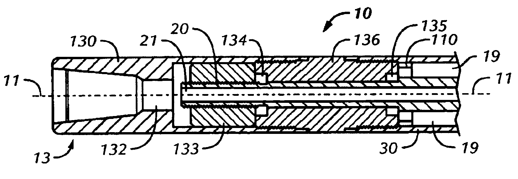
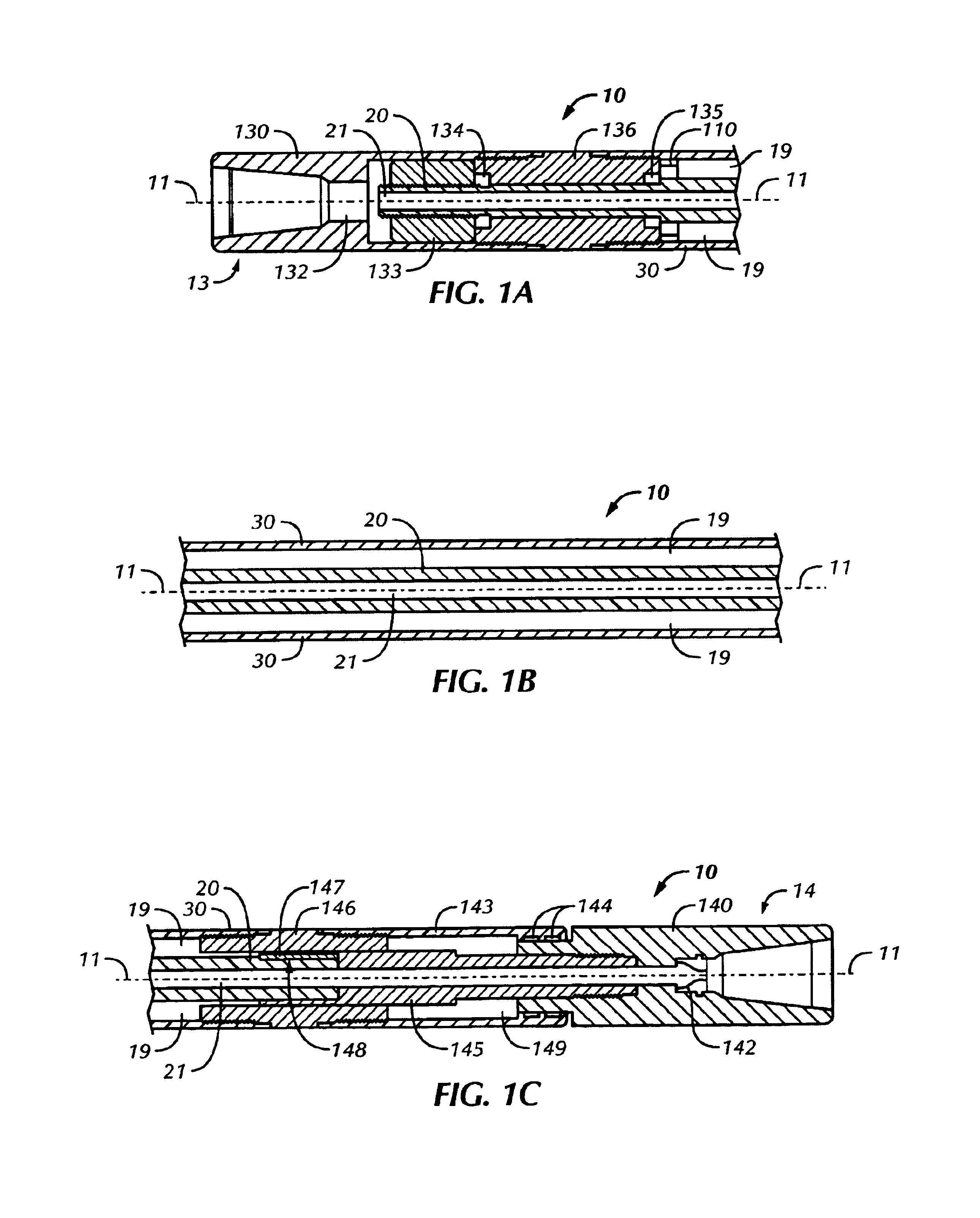
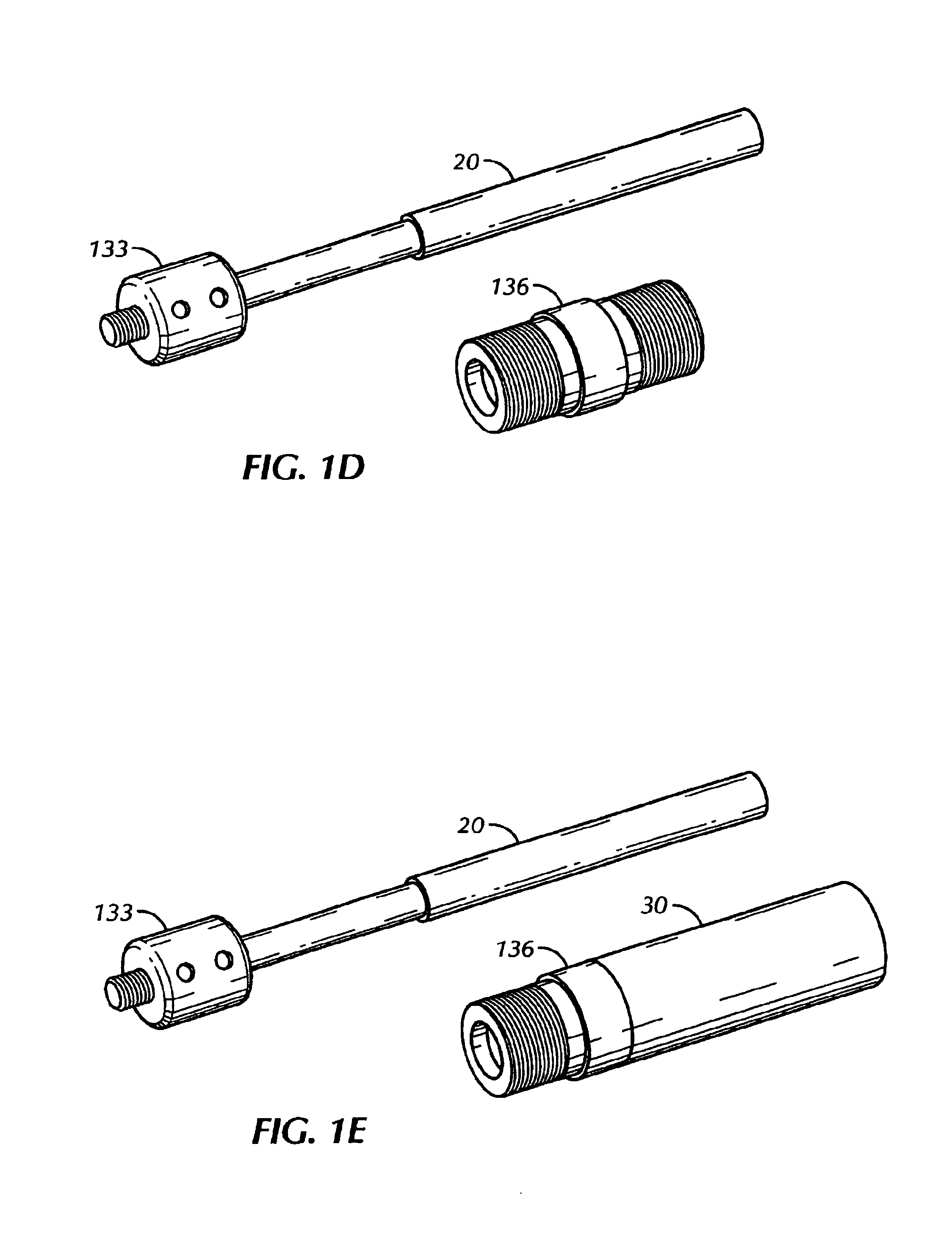
[0093]Referring to FIGS. 1 and 12-15, motor 10 has a core axis 11, which runs through the center of motor 10 between string attachment end 13 and tool attachment end 14. At the axial center of motor 10 is coaxial drive shaft 20, having a coaxial core passageway 21, which provides...


PUM


Abstract

The present invention is a cylindrical linear fluid motor comprising a plurality of reciprocating rotary piston sleeve intermediate an inner coaxial hollow drive shaft and an outer coaxial cylindrical housing. Rotating disc valves at both ends of the sleeve piston control the sequential flow of high-pressure and low-pressure fluid through ports in both the drive shaft and the housing. High-pressure fluid acts on one end of the sleeve piston causing the piston to travel laterally along the drive shaft, with an inner set of roller balls in linear raceways ensuring no rotation between each piston and the drive shaft. The linear motion simultaneously affects exhausting of low-pressure fluid at the other end of the piston. Outer balls are seated in the housing and a sinusoidal circumferential raceway of each piston, to affect rotation in the piston from the lateral motion. As a piston reaches the limit of its linear travel the rotating disc valve on one end closes inlet ports and opens exhaust ports, while another rotating disc valve closes exhaust ports and opens inlet ports at the other end, causing the high-pressure fluid to reverse the piston's lateral direction of movement. The multiple pistons of a motor are rotationally sequenced to create consistent power production throughout 360-degree rotation, of the pistons.

Description

CROSS-REFERENCE TO RELATED APPLICATIONS[0001]This application claims the benefit of U.S. Provisional Application No. 60 / 448,559, filed Feb. 19, 2003.STATEMENT REGARDING FEDERALLY SPONSORED RESEARCH OR DEVELOPMENT[0002]Not Applicable.BACKGROUND OF THE INVENTION[0003]1. Field of the Invention[0004]The invention relates to downhole positive displacement rotary motors of the type used for drilling operations.[0005]2. Description of the Related Art[0006]Linear downhole motors are widely known in the field of drilling operations. Motors are used to develop rotational drive on drilling implements from the drilling fluids forced through the drilling string. Typically, prior art motors use varying configurations of stator and rotor systems. Some examples of prior art systems follow:[0007]U.S. Pat. No. 3,088,529 issued to Cullen et al. on May 7, 1963, discloses a cylindrical fluid-driven downhole engine having a central shaft possessing multiple rotors with moveable vanes contained in shaped ...

Claims


Application Information

Patent Timeline
Patent Type & Authority Patents(United States)
IPC IPC(8): E21B4/02E21B4/00F04B47/00F04B47/08F03C1/00
CPCE21B4/02F03C1/00F04B47/08
Inventor HARTWICK, PATRICK W.
Owner REDIDRILL ENERGY SERVICES
Learn More