Sliding anchorage device

Active Publication Date: 2005-11-08
REEVES ERIC W
View PDF11 Cites 41 Cited by
  • Summary
  • Abstract
  • Description
  • Claims
  • Application Information

AI Technical Summary

Benefits of technology

[0028]The present invention is an anchorage safety device for steelworkers. The anchorage device is adapted to be slidably secured about a flanged structural beam and to which a lanyard may be attached to secure a workman against a fall. The lightweight device may be easily managed by a workman. More

Problems solved by technology

In high rise construction, these activities may take place in an environment subject to wind and weather, as well as subject to the typical construction site hazards of miscommunication, equipment failure or worker mishap.
The fixed devices provide a method for securing a safety line, but inherently limit the steel worker's sp

Method used


Image

  • Sliding anchorage device
  • Sliding anchorage device
  • Sliding anchorage device

Examples


Embodiment Construction

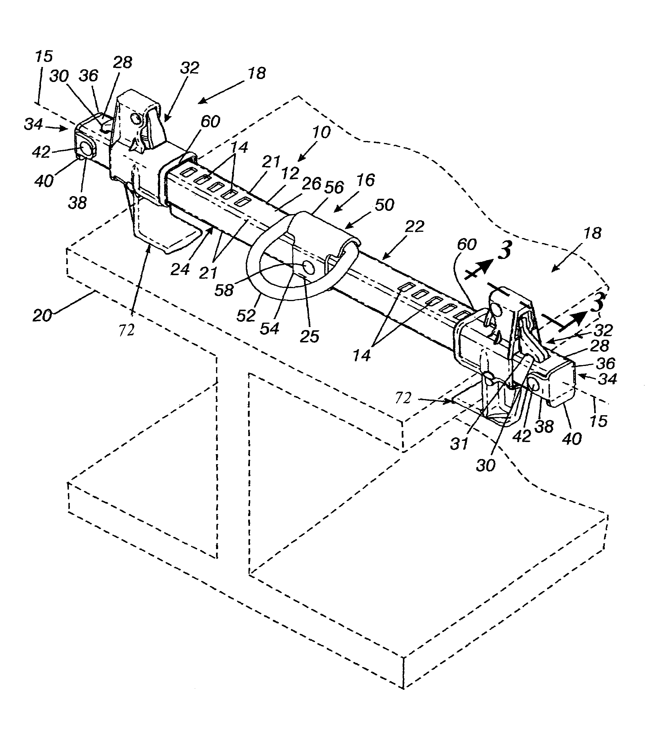
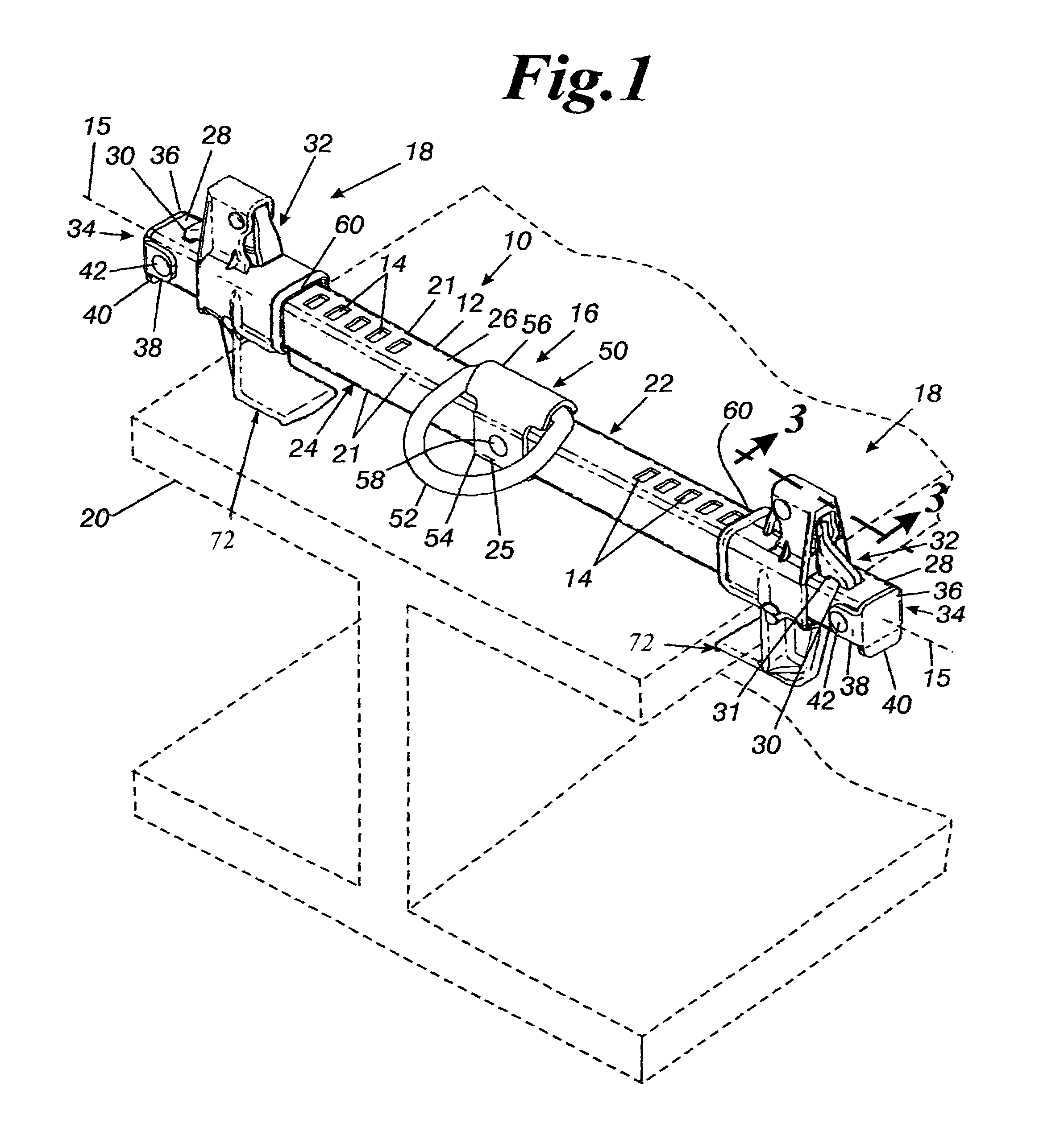
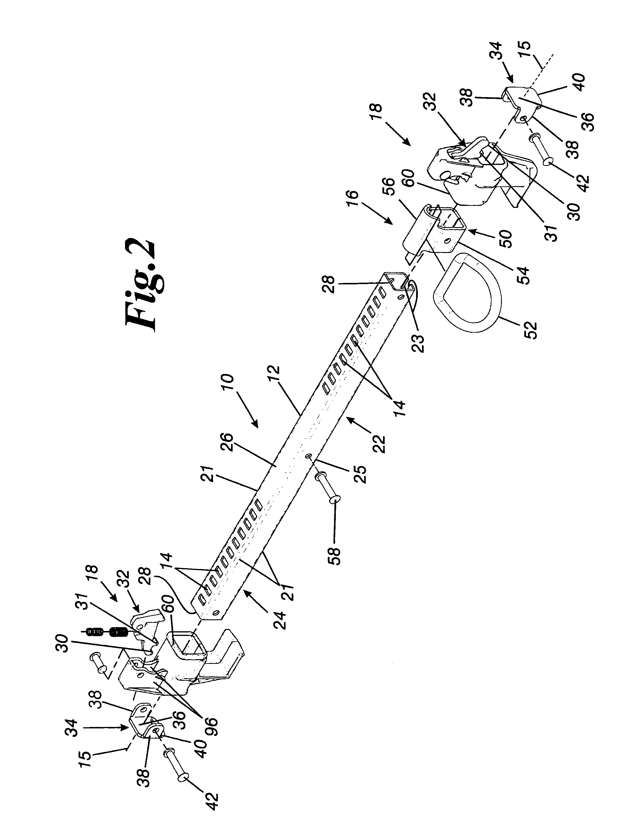
[0044]The present invention is an anchorage safety device for steelworkers. The anchorage device is adapted to be slidably secured about a flanged structural beam and to which a lanyard may be attached to secure a workman against a fall. The lightweight device may be easily managed by a workman. Moreover, with only one hand, the workman may couple or remove the anchorage device from a flanged beam. The device utilizes a pair of novel clamps that secure and maintain the device to a flanged beam. The clamps are configured such that inadvertent disengagement of the device from the beam is obviated.

[0045]Referring to the drawings, and particularly to FIGS. 1 and 2, the invented anchorage device 10 includes an elongate cross-member 12 having a plurality of apertures 14 formed, in series, along its longitudinal axis 15, a lanyard attachment implement 16 to which a worker's lanyard can be clipped, and a pair of opposed clamps 18 for releasably coupling the anchorage device 10 to a flange o...


PUM


Abstract

An anchorage safety device for steelworkers. The safety device is configured to be slidably coupleable to a flanged structural beam to which a lanyard may be attached to secure a workman against a fall. The anchorage device includes an elongate cross-member having a plurality of apertures formed there-through to allow adjustment of the anchorage device to accommodate various beams; a lanyard attachment apparatus, affixed to the mid-point of the cross-member, for receiving a clip of a workman's lanyard; and opposed first and second clamps for coupling the device to the flange of a beam. The clamps include a ratchet pawl having first and second teeth for selectively engaging the cross-member apertures. The worker needs only one hand to release the ratchet pawl from the apertures by simultaneously applying pressure on an enlarged engagement surface of the ratchet pawl and a clamp housing surface that is opposed to the enlarged engagement surface. Since both forces must be simultaneously applied in opposite directions, inadvertent disengagement of the clamp from the cross-member is obviated.

Description

CROSS-REFERENCE TO RELATED APPLCATION[0001]This application claims the benefit of the U.S. Provisional Application No. 60 / 395,429, filed Jul. 13, 2002, and is hereby incorporated by reference.BACKGROUND OF THE INVENTION[0002]1. Field of the Invention[0003]The present invention relates to a method and apparatus for securing a person during construction, and more particularly to a safety device slidably secured about a flanged structural beam to which a lanyard is attached to secure a workman against a fall.[0004]2. Background of the Invention[0005]Construction of steel frame structures, such as industrial plants and office buildings, often involve the necessity for steel workers to work a considerable distance above the ground in order to fasten individual beams and other components together. In high rise construction, these activities may take place in an environment subject to wind and weather, as well as subject to the typical construction site hazards of miscommunication, equipme...

Claims


Application Information

Patent Timeline
IPC IPC(8): A47B96/06E04G3/00A62B99/00A62B1/04E04G21/32
CPCE04G21/3261A62B35/0081A62B35/04E04G5/045E04G21/3276
Inventor REEVES, ERIC W.
Owner REEVES ERIC W
Why Eureka
Try Eureka