Apparatus for exterior evacuation from buildings

Inactive Publication Date: 2005-11-08
LIFE PACK TECH
View PDF29 Cites 63 Cited by
  • Summary
  • Abstract
  • Description
  • Claims
  • Application Information

AI Technical Summary

Benefits of technology

[0007]The preferred embodiment is a self-contained apparatus that can be quickly put on over existing clothing. It has a helmet assembly that contains an air filtration system to provide breathable air to the person at least while he waits to egress the building. It then lowers him to the ground automatically on his own spool of high strength cable alongside the exterior of the building at an average speed of about one foot per second (1 ft/see). Even at that extremely slow speed, it takes a mere twenty-four minutes to reach the ground from the highest occupied floor of either the Sears Tower in Chicago at 1,431 feet, or “Taipei 101” in Taiwan at 1,441 feet—the newest title holder for the world's highest occupied floor. After simple anchorages are installed on every floor, the present invention is well suited for the rapid and safe evacuation of thousands of persons from such tall buildings. In short, the present invention is an apparatus, for 1) providing a means for every person on

Problems solved by technology

Major fires in high rise office buildings and hotels often trap people on the floors above, stranding them to succumb to smoke inhalation, carbon monoxide, and fire, or to leap to their deaths (as nearly 200 did during the WTC disaster).
The low altitude parachutes cannot be used below the 15th floor, and they can collapse if the novice parachutist drifts into the side of his or an adjacent building, something even an experienced parachutist is likely to do.
Tubular net life chutes are limited, both in their numbers and locations in a building, thereby significantly limiting

Method used


Image

  • Apparatus for exterior evacuation from buildings
  • Apparatus for exterior evacuation from buildings
  • Apparatus for exterior evacuation from buildings

Examples


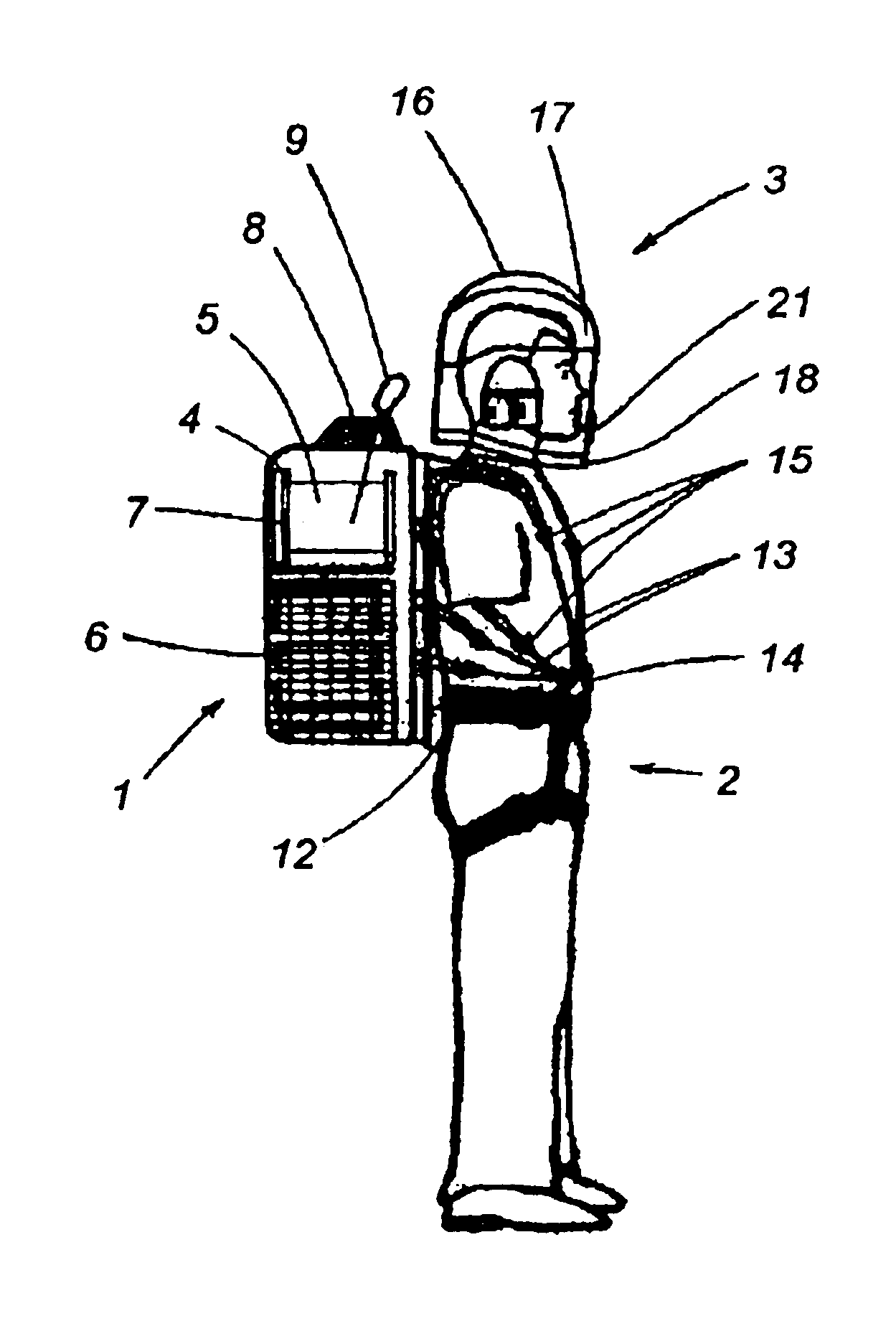
Embodiment Construction

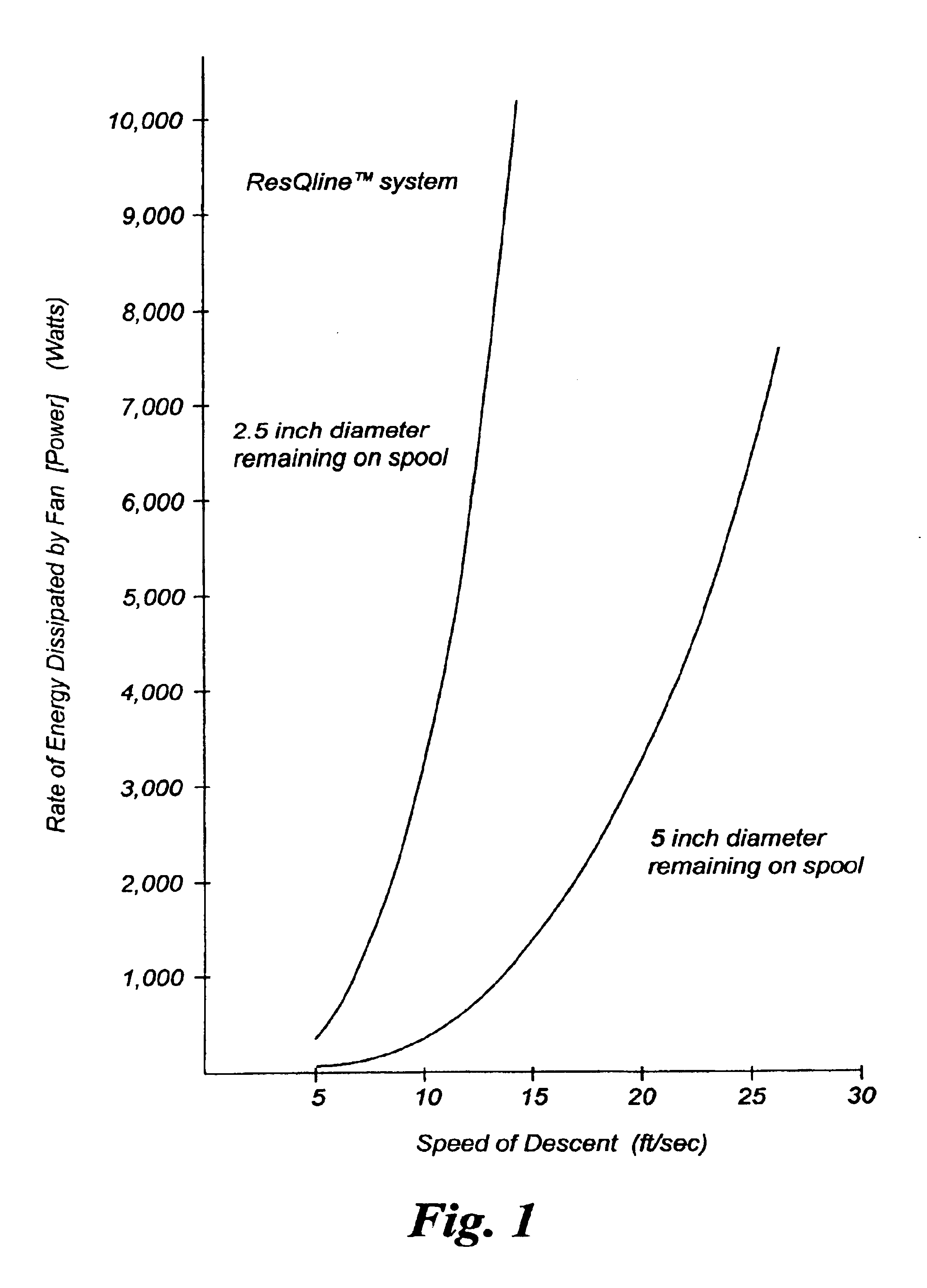
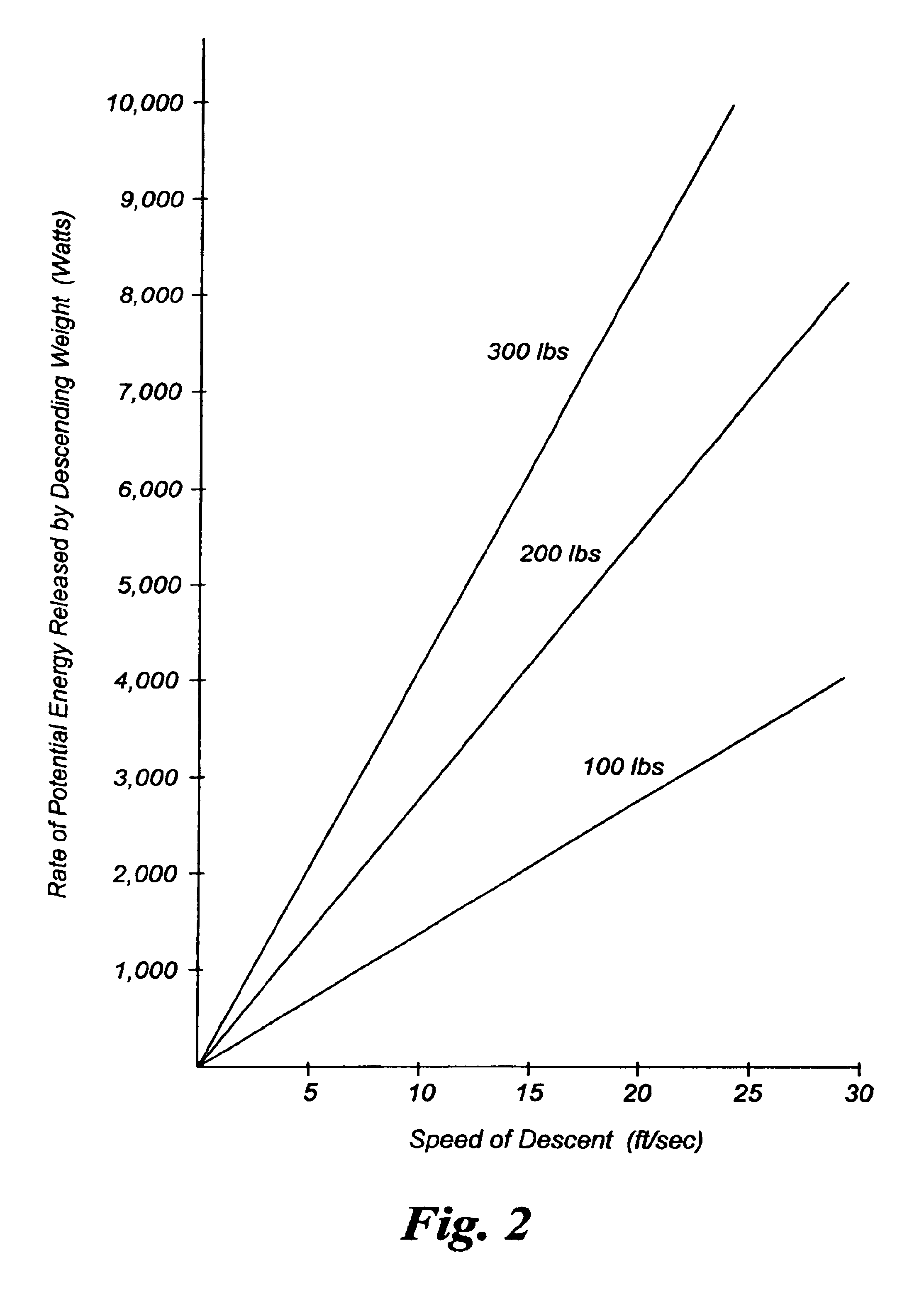
Understanding the Physics

[0023]Picture a 200 pound man about to jump from the window of a burning building from a height of 1,000 feet. He has zero kinetic energy. However, he has 200,000 ft-lbs of potential energy. If he jumps—neglecting the small portion of that energy that gets converted to heat energy by the air resistance as his speed increases—all that potential energy gets converted to 200,000 ft-lbs of kinetic energy which will increase his speed to 252 ft / sec (172 MPH) by the time the unfortunate fellow hits the ground 8 seconds later. What can save him is a mechanism for dissipating all the released potential energy that otherwise goes toward increasing his descent velocity. That descent-slowing, energy-dissipating mechanism would convert the released potential energy into increased random kinetic energy of the individual air molecules that surround the mechanism, with a portion temporarily going into increased random kinetic energy of the individual molecules of the mecha...


PUM


Abstract

An apparatus for safely evacuating a person within a prescribed weight range from a multistory building by enabling the person to exit from the interior of the building to the outside very quickly and to descend to the ground or lower surface alongside the exterior of the building to attain a descent speed of less than four feet per second to land injury-free, the apparatus comprising a housing, a harness affixed to the housing for affixing the housing to the person, a cable of predetermined length within the housing, having a free-end with a securing member for affixing it to an anchorage proximate the descent point, and a descent slowing energy dissipating mechanism within the housing driven by the playout of the cable as the person descends, which enables the person to attain automatically within his descent a descent speed of less than four feet per second determined by the intersection of the graph of the curve that describes the rate of energy dissipated as a function of the descent speed and the graph of the line that describes the rate of potential energy released by the total descending weight as a function of descent speed where the slove of the graph of the rate of energy dissipated curve exceeds the slone of the graph of the rate of potential energy released line.

Description

CROSS REFERENCE TO RELATED APPLICATIONS[0001]This application claims priority from Provisional Application Ser. No. 60 / 449,125 filed Feb. 21, 2003, Provisional Application No. 60 / 468,845 filed May 8, 2003, and Provisional Application Ser. No. 60 / 492,398 filed Aug. 4, 2003.BACKGROUND OF THE INVENTION[0002]The World Trade Center disaster in New York City on Sep. 11, 2001 has highlighted the need for an apparatus to provide for the rapid and safe evacuation of large numbers of persons along the exterior of a high-rise building during a major fire or other life-threatening emergency when the stairwells are inaccessible, unusable, overcrowded, smoke-filled, obstructed, or otherwise unsafe.[0003]Major fires in high rise office buildings and hotels often trap people on the floors above, stranding them to succumb to smoke inhalation, carbon monoxide, and fire, or to leap to their deaths (as nearly 200 did during the WTC disaster). Thus there exists the need for an apparatus capable of getti...

Claims


Application Information

Patent Timeline
IPC IPC(8): A62B1/08A62B1/00
CPCA62B1/08A62B5/00
Inventor LEON, ROBERT L.
Owner LIFE PACK TECH
Why Eureka
Try Eureka