Backlight device and liquid crystal display

a liquid crystal display and backlight technology, applied in the field of backlight devices or lighting devices, can solve the problems of high brightness, difficult to achieve high resolution, complex fabrication, etc., and achieve the effect of stable light intensity, stable display brightness, and stable light power of mercury-free fluorescent lamps

Inactive Publication Date: 2005-11-08
PANASONIC CORP
View PDF8 Cites 16 Cited by
  • Summary
  • Abstract
  • Description
  • Claims
  • Application Information

AI Technical Summary

Benefits of technology

[0009]Since the backlight device is provided with mercury-free fluorescent lamps the light power thereof is unaffected by ambient temperature, the intensity of the light emerging from the light guide plate is stable. Specifically, rotation of the rotary member causes heat exchange between the arc tube of each mercury-free fluorescent lamps mounted on the rotary member and the surrounding air, resulting in that the ambient temperature of the mercury-free fluorescent lamp varies over a relatively wide range. However, notwithstanding such changes in ambient temperature, the light power of the mercury-free fluorescent lamp is stable. Accordingly, by using the backlight device of the present invention, a field sequential co

Problems solved by technology

This type of color liquid crystal display needs to use at least thee pixels or cells on the liquid crystal display panel corresponding to red (R), green (G), and blue (B) as a group for produce of a color image, thereby causing difficulty in achieving a high resolution.
Further, since the color filters need to be positioned highly precisely with respect to the liquid crystal display panel, the complexity of fabrication increases.
Furthermore, high brightness cannot be obtained due to absorption of light by the color filters.
However, using mercury fluorescent lamps in field sequential color liquid crystal display apparatuses involves the following problems.
Thus, neither of the above conventional backlight devices can illuminate the liquid crystal display panel with stable intensity.
In particular, in the case of the backlight device of the Japanese Patent Application Laid-open Publication No. 2000-331520, the ambient temperature of each mercury-type fluorescent lamp varies widely due t

Method used


Image

  • Backlight device and liquid crystal display
  • Backlight device and liquid crystal display
  • Backlight device and liquid crystal display

Examples


first embodiment

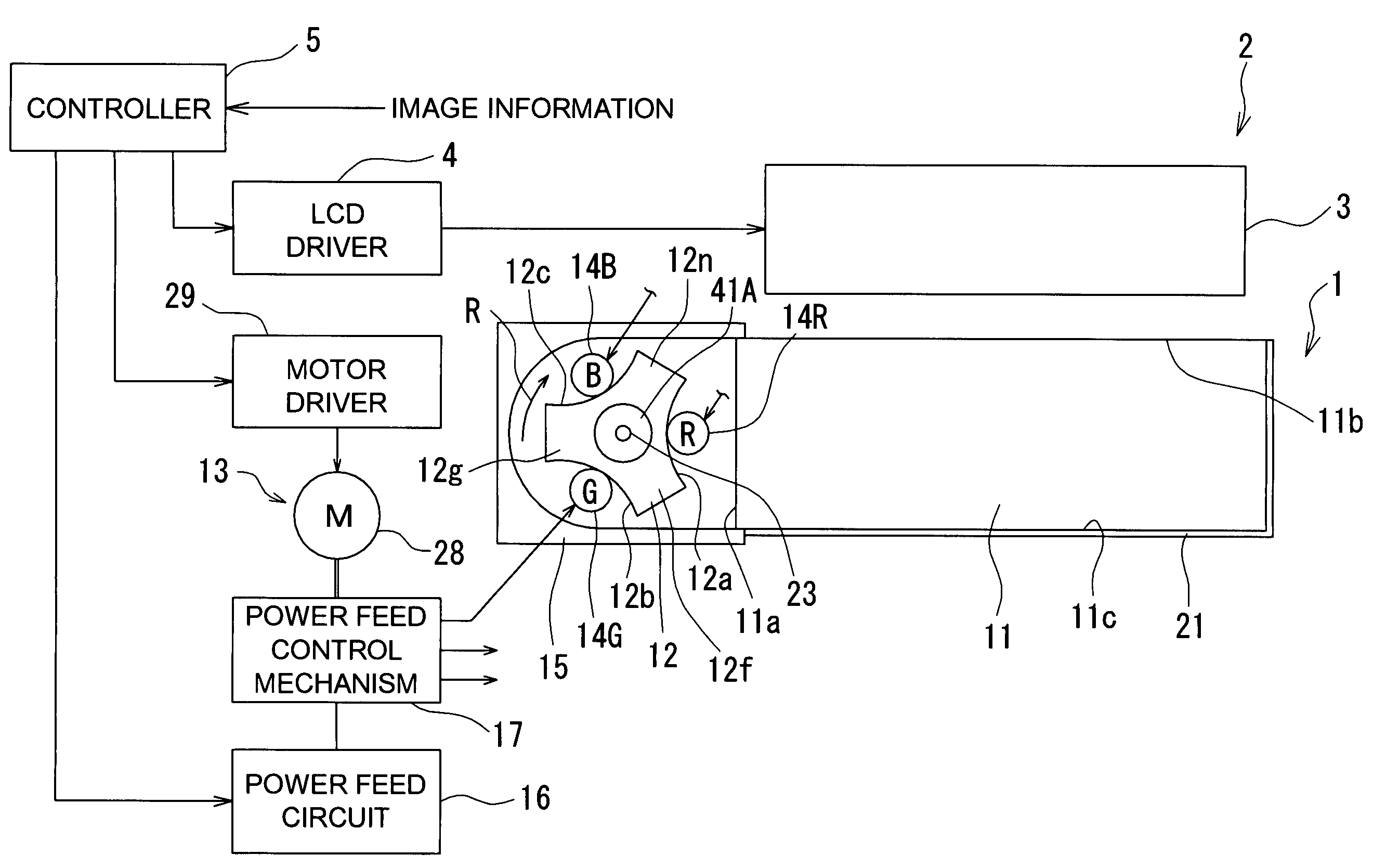
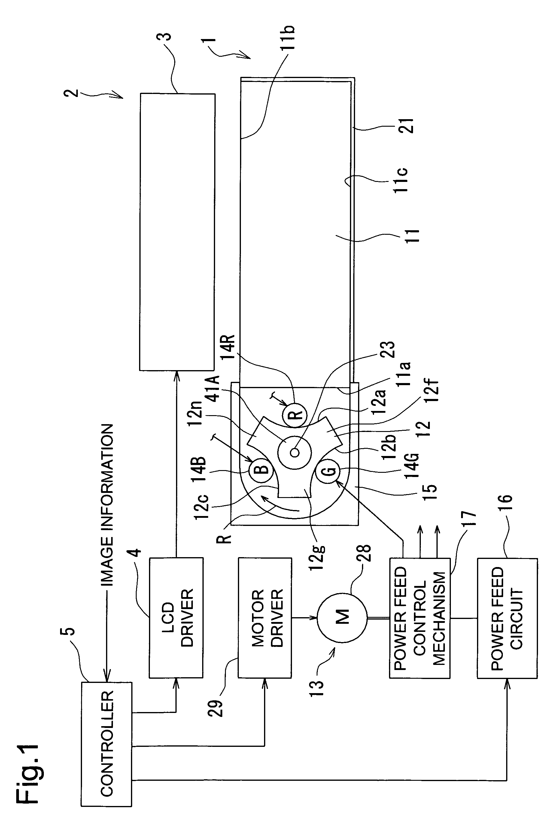
[0043]FIG. 1 shows a liquid crystal display apparatus 2 provided with an edge lighting type backlight device 1 according to a first embodiment of the present invention.

[0044]The backlight device 1 is mounted behind the rear surface of a liquid crystal display panel 3. The liquid crystal display panel 3 has a known construction where transparent electrodes and a liquid crystal material are sealed between a pair of glass plates. An LCD driver 4 is provided for driving the liquid crystal display panel 3 to perform shuttering. The LCD driver 4 is controlled by a controller 5 in accordance with image information. The construction of the liquid crystal display panel 3 is not limited to any specific type. The present invention can be applied not only to liquid crystal displays but also to other passive displays.

[0045]The backlight device 1 comprises a light guide plate 11, a rotary member 12, a rotary drive mechanism 13, three mercury-free fluorescent lamps 14R, 14G, and 14B, a reflection ...

second embodiment

[0075]FIG. 17 shows an edge lighting type backlight device 1 according to a second embodiment of the present invention. A pair of opposite edge faces of the light guide plate 11 serve as light incident faces 11a and 11d. The rotary members 12A and 12B, each mounted with mercury-free fluorescent lamps 14R to 14B, are disposed facing the respective light incident faces 11a and 11d. By introducing light through the pair of opposite light incident faces 11a and 11d, evenly spread light can be made to exit from the light emission face 11b even when the area size of the light guide plate 11 is large. The controller 5 synchronizes the rotation of the two rotary members 12A and 12b by controlling their corresponding two motors 28 and 28. Specifically, the two rotary members 12A and 12b are rotated at the same rotational speed. Of the mercury-free fluorescent lamps 14R to 14B on the rotary members 12A and 12B, the lamps emitting light of the same color are simultaneously positioned opposite ...

third embodiment

[0076]FIG. 18 shows a liquid crystal display apparatus 2 equipped with a rear lighting type backlight device 1 according to a third embodiment of the present invention. The face 11c on the side opposite to the light emission face 11b of the light guide plate 11 functions as the light incident face, and the rotary member 12 with the mercury-free fluorescent lamps 14R to 14B mounted thereon is disposed facing this light incident face 11c. Reflecting films 21 are formed on both edge faces 11a and 11d of the light guide plate 11. Since the opposite face 11c has a larger area than the edge faces 11a and 11d, it is desirable that the recessed portions 12a to 12c of the rotary member 12 is each formed in the shape of an arc having a wider opening than the recessed portions 12a to 12c of the first embodiment (see FIGS. 1 and 2) so that the light emitted from the respective mercury-free fluorescent lamps 14R to 14B efficiently enters the opposite face 11c. In FIG. 18, reference numeral 66 is...


PUM


Abstract

A backlight device has a light guide plate, a rotary member, a rotary drive mechanism for rotating the rotary member, a plurality of mercury-free fluorescent lamps, and a power feed control mechanism. Each of the mercury-free fluorescent lamps has an arc tube mounted on the rotary member so as to extend parallel to the rotary shaft, a mercury-free discharge medium consisting of a rare gas sealed within the arc tube, and first and second electrodes for exciting the discharge medium. The mercury-free fluorescent lamps respectively emit lights of different colors. The emitted light enters the light guide plate through its light incident face and emerges from its light emission face.

Description

RELATED APPLICATION[0001]This application claims priority from Japanese Patent Application No. 2002-210731, the entire content of which is incorporated herein by reference.BACKGROUND OF THE INVENTION[0002]The present invention relates to a backlight device or a lighting device, and more particularly to a backlight device used in a field sequential display apparatus including a liquid crystal display apparatus.[0003]Some conventional color liquid crystal displays are equipped with color filters arranged on a liquid crystal display panel. This type of color liquid crystal display needs to use at least thee pixels or cells on the liquid crystal display panel corresponding to red (R), green (G), and blue (B) as a group for produce of a color image, thereby causing difficulty in achieving a high resolution. Further, since the color filters need to be positioned highly precisely with respect to the liquid crystal display panel, the complexity of fabrication increases. Furthermore, high br...

Claims


Application Information

Patent Timeline
IPC IPC(8): F21V8/00F21V17/02F21V17/00G02F1/1335G02F1/13G02F1/13357
CPCG02B6/0068F21V17/02F21Y2103/00F21Y2113/00G02F2001/133622G02F1/133622
Inventor YAMAMOTO, NORIKAZU
Owner PANASONIC CORP
Why Eureka
Try Eureka