Method and device for real-time monitoring and feedback of optical power

A real-time monitoring and feedback device technology, which is applied in the field of laser confocal microendoscopy, can solve the problems of inability to truly restore the target's brightness and darkness changes, image distortion, etc., and achieve the effect of improving image restoration accuracy and ensuring accuracy

Active Publication Date: 2018-07-31
JINGWEI SHIDA MEDICAL TECH WUHAN CO LTD
View PDF4 Cites 0 Cited by
  • Summary
  • Abstract
  • Description
  • Claims
  • Application Information

AI Technical Summary

Problems solved by technology

[0006] In view of the above defects or improvement needs of the prior art, the present invention provides a method and device for real-time monitoring and feedback of optical power, which are used in the laser confocal microendoscope system. The restoration of the brightness and darkness changes of the restoration target in the speculum system is studied, and the key factor that affects the image restoration distortion is the stability of the laser light power. Further, by ensuring the stability of the laser power, the accurate restoration of the image is realized, thereby solving the current problem. The advanced laser confocal microendoscopy system cannot truly restore the brightness and darkness changes of the target, resulting in image distortion

Method used


Image

  • Method and device for real-time monitoring and feedback of optical power
  • Method and device for real-time monitoring and feedback of optical power
  • Method and device for real-time monitoring and feedback of optical power

Examples


Embodiment Construction

[0032] In order to make the object, technical solution and advantages of the present invention clearer, the present invention will be further described in detail below in conjunction with the accompanying drawings and embodiments. It should be understood that the specific embodiments described here are only used to explain the present invention, not to limit the present invention.

[0033] In addition, the technical features involved in the various embodiments of the present invention described below can be combined with each other as long as they do not constitute a conflict with each other.

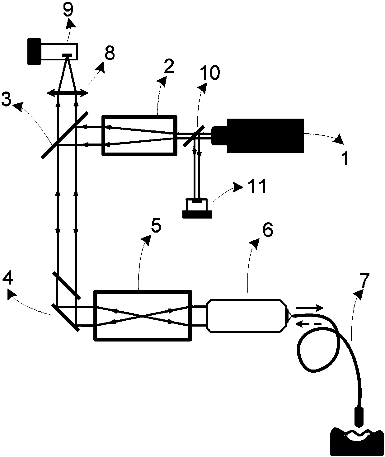
[0034] figure 1 It is a schematic diagram of an optical power real-time monitoring and feedback device according to an embodiment of the present invention. like figure 1 As shown, the principle of the confocal microendoscope is usually: the laser light emitted by the laser 1 is reflected by the beam expander 2 and the dichroic mirror 3 and then enters the two-dimensional scanning mech...


PUM


Abstract

The invention discloses a real-time optical power monitoring and feedback method comprising the steps of: S1, inserting a light splitting slice into a collimation optical path of a confocal microscopic endoscope for splitting light in the optical path so that a small part of the light is reflected and most of the light transmits the light splitting slice; S2, disposing a photoelectric detector in a direction perpendicular to the traveling direction of the light in order to receive a light intensity signal reflected by the light splitting slice, to convert the light intensity signal into an electric signal, and to transmit the electric signal to a control circuit; and S3, enabling the control circuit to obtain the optical power entering an optical path system, and sending a signal to the control circuit in a negative feedback way when the optical power is abnormal, and controlling a laser to output correct optical power so as to guarantee stable laser power entering the laser confocal microscopic endoscope system. The present invention also discloses a corresponding monitoring and feedback device. The method and device can monitor the optical power of the confocal microscopic endoscope system in real time, and can prevent system signal distortion caused by the abnormal optical power in a used process, and greatly enhance system reliability.

Description

technical field [0001] The invention belongs to the technical field of laser confocal microendoscopes, in particular to a method and device for real-time monitoring and feedback of optical power in a laser confocal microendoscope system. Background technique [0002] Confocal endoscopy (CLE) is a derivative technology of confocal microscopy. It is mainly used in the fields of medicine and biology. Currently, the probe confocal endoscopy (pCLE) is widely used in clinical practice. Clinically, the probe-type confocal microendoscope uses an image transmission fiber bundle composed of tens of thousands of optical fibers to transmit the image of the tissue structure in the human body to the display device for reading and interpretation. [0003] The confocal microendoscope host uses a two-dimensional scanning mechanism composed of a galvanometer-type galvanometer / resonant-type galvanometer to deflect the excitation laser beam in a two-dimensional plane, and the deflected beam pas...

Claims


Application Information

Patent Timeline
Patent Type & Authority Patents(China)
IPC IPC(8): G01J1/00G01J1/42G05D25/02A61B1/00
CPCA61B1/00064A61B1/00165A61B1/00172G01J1/00G01J1/4257G05D25/02
Inventor 万勇冯宇段西尧马骁萧
Owner JINGWEI SHIDA MEDICAL TECH WUHAN CO LTD
Why Eureka
Try Eureka