Apparatus and method for driving a plasma display panel

a plasma display panel and apparatus technology, applied in the direction of instruments, static indicating devices, etc., can solve the problems of complex structure of the driving circuit, limited current, and inability to completely operate the conventional sustain-discharge circui

Inactive Publication Date: 2005-11-08
SAMSUNG SDI CO LTD
View PDF10 Cites 20 Cited by
  • Summary
  • Abstract
  • Description
  • Claims
  • Application Information

AI Technical Summary

Benefits of technology

[0011]In accordance with the present invention a PDP driving circuit is provided which is capable of recovering power.

Problems solved by technology

On the other hand, in the case of the AC PDP, the current is restricted due to the natural formation of capacitance because a dielectric layer covers the electrodes.
However, the conventional sustain-discharge circuit can completely operate only when the power recovery circuit charges a voltage corresponding to half of the external power in order to re-use power using the resonance of an inductor and the capacitive load (a panel capacitor).
Accordingly, a structure of a driving circuit is complicated and a large amount of devices must be used in manufacturing the driving circuit.

Method used


Image

  • Apparatus and method for driving a plasma display panel
  • Apparatus and method for driving a plasma display panel
  • Apparatus and method for driving a plasma display panel

Examples


first embodiment

[0044]The sustain-discharge circuit 320 according to the present invention will now described in detail with reference to FIGS. 2 and 3.

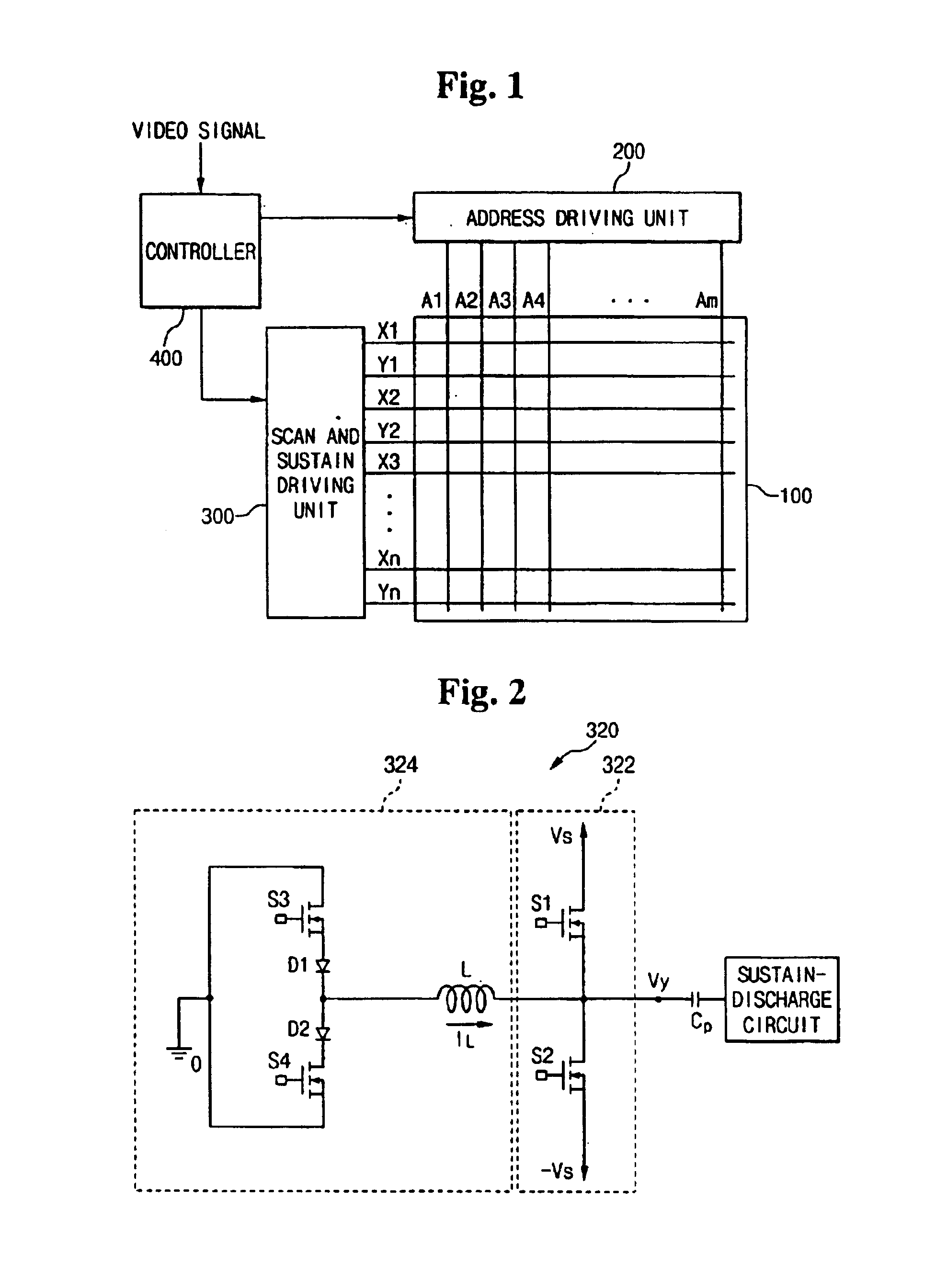
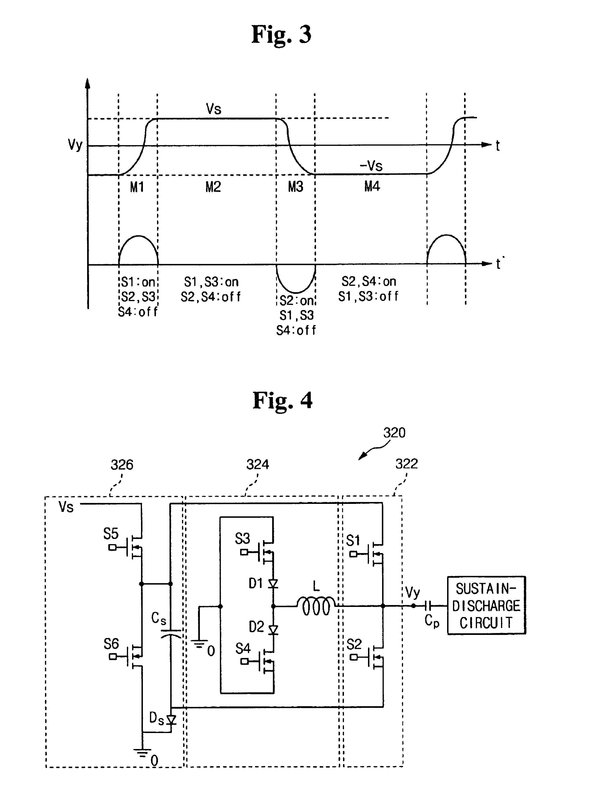
[0045]FIG. 2 is a circuit diagram showing the sustain-discharge circuit of the PDP according to the first embodiment of the present invention. FIG. 3 is a timing diagram showing the driving of the sustain-discharge circuit of the PDP according to the first embodiment of the present invention.

[0046]As shown in FIG. 2, sustain-discharge circuit 320 according to the first embodiment of the present invention includes sustain-discharge unit 322 and power recovering unit 324. Sustain-discharge unit 322 includes switching elements S1 and S2 serially connected to each other between power source Vs and power source −Vs. The contact point of switching elements S1 and S2 is connected to an electrode (assumed to be a Y electrode) of a plasma panel (a panel capacitor Cp because the plasma panel operates as capacitive load). Power sources Vs and −Vs supply voltag...

second embodiment

[0059]As shown in FIG. 4, sustain-discharge circuit 320 according to the present invention further includes power source unit 326. Power source unit 326 includes switching elements S5 and S6. Switching elements S5 and S6 are serially connected to each other between power source Vs and ground. Capacitor Cs is connected between the contact point of switching elements S5 and S6 and switching element S2 of sustain-discharge unit 322. The contact point of switching elements S5 and S6 is connected to switching element S1. Diode Ds is connected between capacitor Cs and ground. Accordingly, voltage −Vs can be applied to panel capacitor Cp using the voltage charged to capacitor Cs without a power source −Vs.

[0060]The operation of the sustain-discharge circuit according to the second embodiment of the present invention will now be described with reference to FIG. 5 on the basis of a difference between the first embodiment and the second embodiment.

[0061]As shown in FIG. 5, the driving time ac...

third embodiment

[0073]Also, Y electrode Vy of panel capacitor Cp is sustained to be voltage Vs by turning on switching element S1. At this time, because switching element S1 is turned on in a state where a voltage between a drain and a source is 0, switching element S1 can perform zero voltage switching. Accordingly, the turn-on switching loss of switching element S1 is not generated. Because the energy accumulated in inductor L is used in the third embodiment, it is possible to increase Y electrode voltage Vy to Vs even when a parasitic component exists in the sustain-discharge circuit. That is, the zero voltage switching can be performed even when the parasitic component exists in the circuit.

[0074]As shown in FIG. 10D, in the mode 4 (M4), switching element S1 continuously is turned on. Accordingly, Y electrode voltage Vy of panel capacitor Cp is continuously sustained to Vs and switching element S3 is turned off when current IL that flows through the inductor decreases to 0 A.

[0075]In a mode 5 (...


PUM


Abstract

A plasma display panel sustain-discharge circuit. First and second signal lines for supplying first and second voltages and at least one inductor coupled between one end of the panel capacitor and a third voltage are formed. Energy is stored in the inductor through a path formed between the third voltage and the first signal line in a state where a voltage of one end of the panel capacitor is substantially fixed to the first voltage. The voltage of one end of the panel capacitor substantially decreases to the second voltage using resonance current generated between the inductor and the panel capacitor and the stored energy. Energy is stored in the inductor through a path formed between the third voltage and the second line in a state where a voltage of one end of the panel capacitor is substantially fixed to the second voltage. The voltage of one end of the panel capacitor substantially increases to the first voltage using the resonance current generated between the inductor and the panel capacitor and the stored energy.

Description

CROSS REFERENCE TO RELATED APPLICATIONS[0001]The present invention claims priority to and the benefit of Korean Patent Application No. 2001-0047311 filed on Aug. 6, 2001 and Korean Patent Application No. 2002-0013573 filed on Mar. 13, 2002.BACKGROUND OF THE INVENTION[0002](a) Field of the Invention[0003]The present invention relates to an apparatus and a method for driving a plasma display panel (PDP) and, in particular, a PDP sustain-discharge circuit.[0004](b) Description of the Related Art[0005]In general, a plasma display panel (PDP) is a flat plate display for displaying characters or images using plasma generated by gas discharge. Pixels ranging from hundreds of thousands to more than millions are arranged in the form of a matrix according to the size of the PDP. PDPs are divided into direct current (DC) PDPs and alternating current (AC) PDPs according to the shape of the waveform of an applied driving voltage, and the structure of a discharge cell.[0006]Current directly flows...

Claims


Application Information

Patent Timeline
Patent Type & Authority Patents(United States)
IPC IPC(8): G09G3/28G09G3/20G09G3/288G09G3/291G09G3/294G09G3/296G09G3/298
CPCG09G3/294G09G3/2965G09G3/291G09G2330/02
Inventor LEE, JOO-YULKANG, KYOUNG-HOKIM, HEE-HWAN
Owner SAMSUNG SDI CO LTD
Why Eureka
Try Eureka