Method Of Equipments Integration For A Complex Electrical Heart And Module Of Implementation

a technology of complex electrical heart and equipment, applied in the construction details of electrical apparatus, substation/switching arrangement casing, printed circuit board receptacle, etc., can solve the problems of complex installation, difficult integration of the “electrical power centre” function, and large component size of the electrical system, so as to simplify the electrical connection of the equipment, facilitate maintenance, and facilitate the effect of access to each piece of equipmen

Active Publication Date: 2012-10-25
AIRBUS OPERATIONS (SAS)
View PDF11 Cites 1 Cited by
  • Summary
  • Abstract
  • Description
  • Claims
  • Application Information

AI Technical Summary

Benefits of technology

[0023]The invention aims at getting rid from such disadvantages through simplifying the electrical connections of the equipment while allowing for a good accessibility of each piece of equipment and an easier maintenance. The in...

Problems solved by technology

In such conditions, the component size in the electrical system increases substantially and the installation becomes more complex, in particular the implementing means for the electrical power centre function.
The integration of the “electrical power centre” function has thus turned out problematical due to the complexity thereof and to the new requirements dictated by safety (for instance, doubling the voltage) as well as to the environmental structures in a composite material based on carbon fibers.
The cargo compartment area dedicated to the electrical power centre function is now saturated in terms of congestion, in particular with the number of interconnecting cables between electrical boxes.
The maintenance of such area may become delicate.
For practical reasons such as congestion, mass, high heat dissipation, problematic electrical connections, electromagnetic disturbances, such power boxes are not integrated into the main box.
The complexity of the ...

Method used


Image

  • Method Of Equipments Integration For A Complex Electrical Heart And Module Of Implementation
  • Method Of Equipments Integration For A Complex Electrical Heart And Module Of Implementation
  • Method Of Equipments Integration For A Complex Electrical Heart And Module Of Implementation

Examples


Embodiment Construction

[0044]The terms “upper” and derivatives, “lower” and derivatives relate, as well as “vertical” and derivatives, to a relative localization of elements or element parts positioned in operation or equivalent.

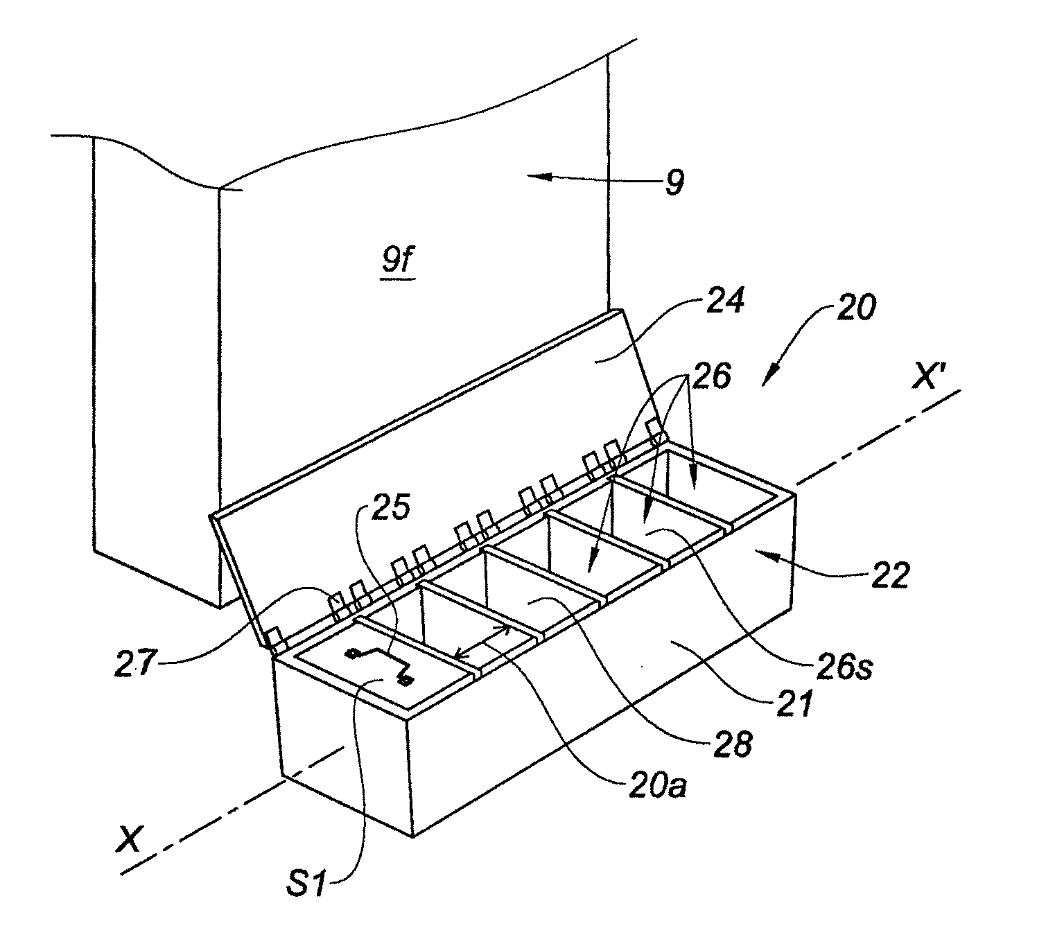
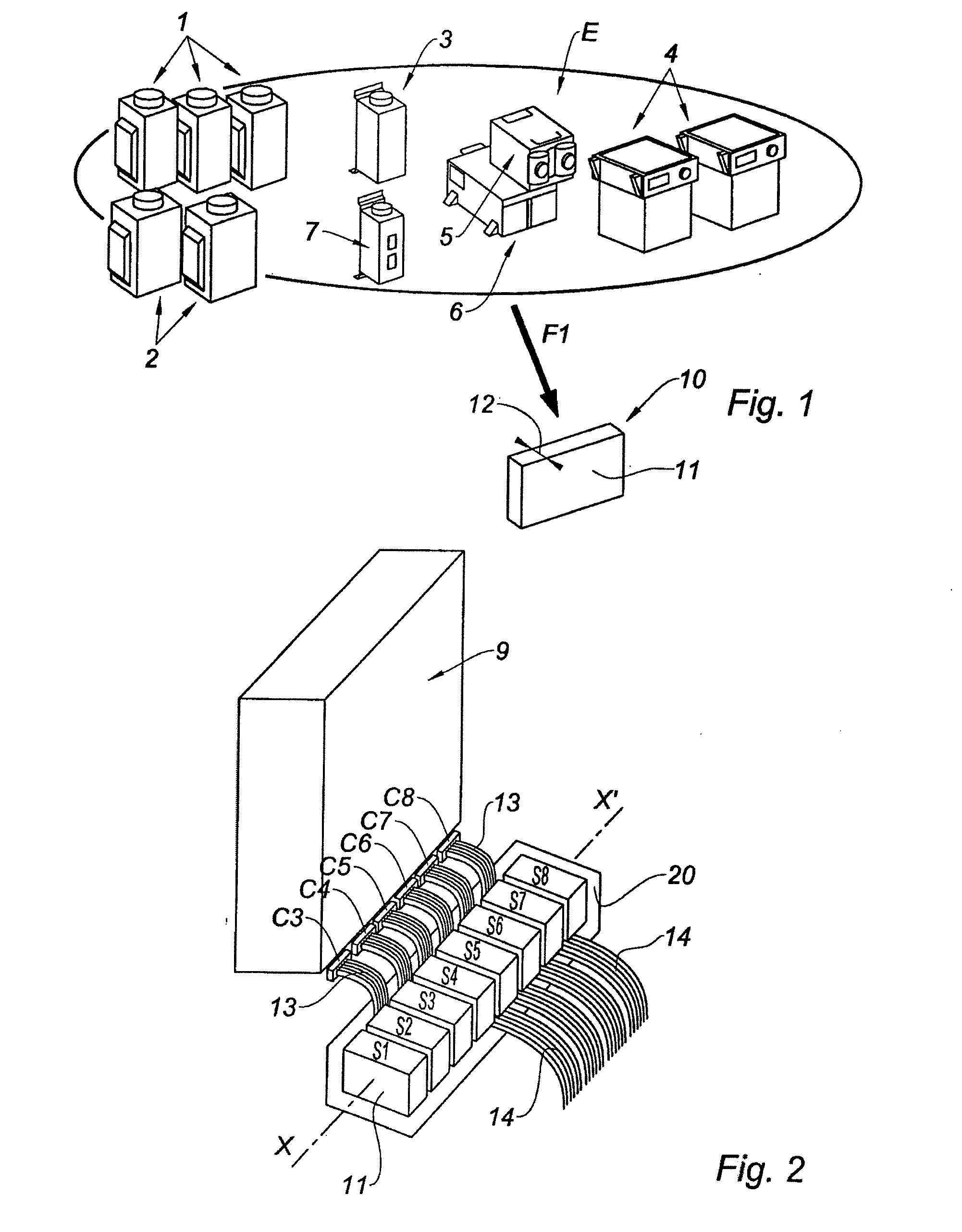
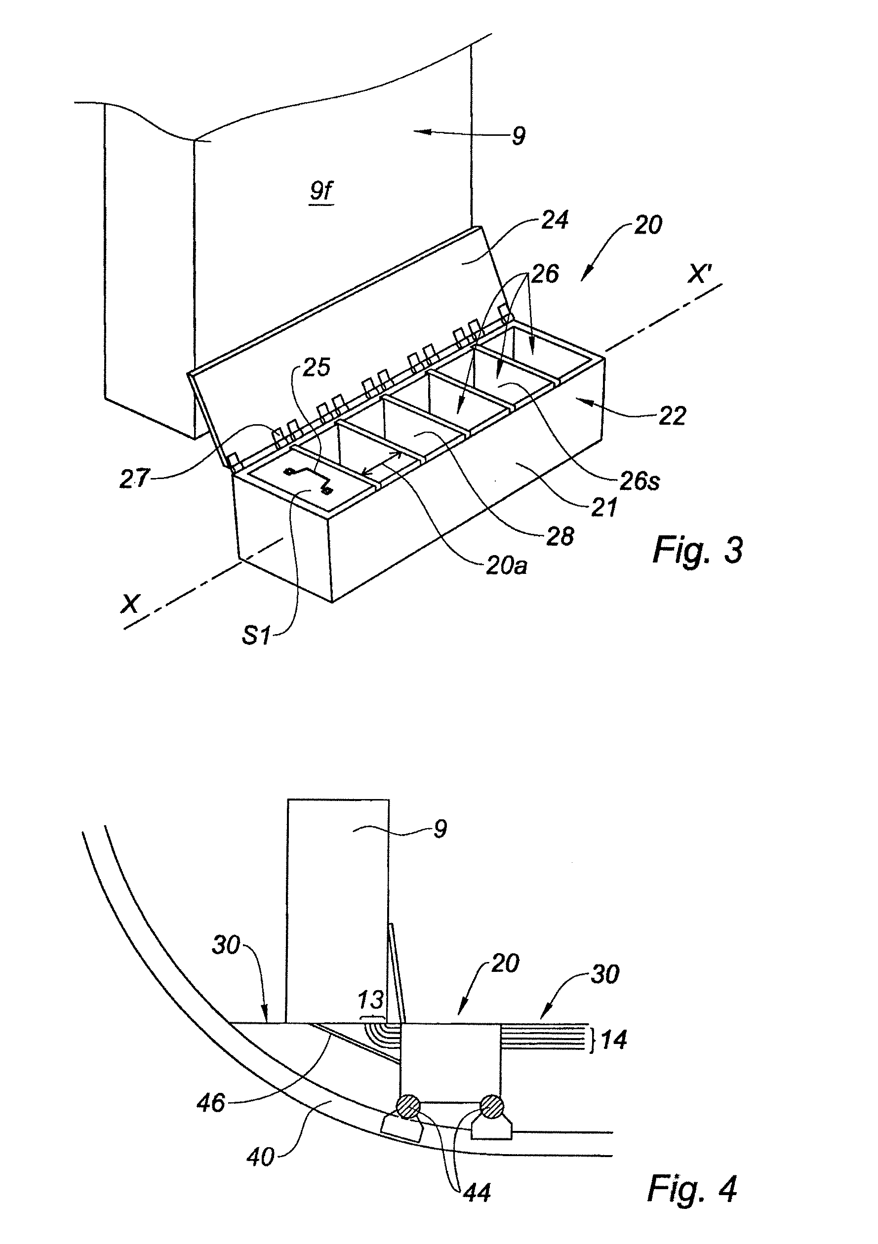
[0045]Referring to FIG. 1, the set E illustrates electrical equipment of an electrically autonomous structure, a plane in the example. This equipment has different sizes. There can be mentioned three autotransformers (AT), two transformers-current rectifiers (TR) 2, a static undulator 3, two batteries 4 and pieces of equipment 5 to 7 associated with the electrical power centre so as to be applied to the APU (auxiliary power unit). The “electrical power centre” function is divided into two independent boxes or power centres 9 (only the left power centre is represented on the Figs.).

[0046]Each of the pieces of equipment 1 to 7 is formatted (arrow F1) according to a model 10 in a wholly parallelepipedic shape with a main section 11 of a determined size. Such formatting is made possib...


PUM

PropertyMeasurementUnit
Poweraaaaaaaaaa
Volumeaaaaaaaaaa
Shapeaaaaaaaaaa

Abstract

The invention aims at simplifying the electrical connections between equipment and an electrical power centre to be supplied in electricity, while enabling a good accessibility of each piece of equipment and an easier maintenance. To do so, a particular integration of this equipment is carried out so as to be able to assemble them together and connect them in a direct extension of the electrical power centre. According to one embodiment, an integration module consists in a frame and a cover, the frame having a substantially parallelepipedic shape adapted to be able to extend longitudinally along a main axis in parallel with a longitudinal main side of the electrical power centre of the structure to be supplied. Cells of constant section and a width being adjustable by movable intermediary walls, extend perpendicularly to the main axis. Such cells are adapted to receive formatted electrical equipment.

Description

TECHNICAL FIELD[0001]The invention relates to a method for integrating equipment for a complex electrical power centre in a structure to be electrically supplied, in particular for a plane power centre. The invention also relates to an electrical power integrating module adapted for implementing the method. The invention applies particularly to commercial planes of a conventional electric generation being in operation nowadays.[0002]Thus, in a main application, but not exclusively, the invention relates to the electrical system on board planes. In such a system, an “electrical power centre” function is conventionally integrated into a technical cargo compartment of the plane so as to manage and distribute electrical power for all consumers. Such management is structured depending on the different operating modes being predefined according to the flight phases and conditions, in particular depending on predetermined failure cases.[0003]Owing to the present tendency to the “all-electr...

Claims


Application Information

Patent Timeline
IPC IPC(8): H02B1/26H05K13/00
CPCH02G3/00Y10T29/49117H05K7/1432H05K7/14325
Inventor GUERING, BERNARD
Owner AIRBUS OPERATIONS (SAS)
Why Eureka
Try Eureka