
Stand arrangement for a medical-optical instrument

a technology of optical instruments and stands, applied in the field of stand arrangements for medical optical instruments, can solve the problems of only very large attenuation of vibrations of holding units, and achieve the effect of preventing disturbing vibrations of surgical microscopes accommodated on the stand, good mechanical balancing of the stand arrangement, and optimal movability

Inactive Publication Date: 2005-11-08
CARL ZEISS SMT GMBH
View PDF4 Cites 10 Cited by
  • Summary
  • Abstract
  • Description
  • Claims
  • Application Information

AI Technical Summary

Benefits of technology

[0006]In this way, a stand arrangement is provided wherein a coupling mechanism of a holding unit and the fourth link can be accommodated in the first link. This makes possible a compact configuration of the stand arrangement and reduces the danger of squeezing which occurs during operation of the arrangement. A force surface contact with increased inner friction is produced in that a coupling of the holding unit and the fourth link takes place via toothed wheel gear assemblies. This causes vibrations of the holding unit (which vibrations can possibly come from the building) to be transmitted only very greatly attenuated to the medical-optical equipment accommodated on the arrangement.
[0015]In a further embodiment of the invention, a control loop (open loop or closed loop) is coupled to an electric motor. Signals of an angle sensor and / or a distance sensor and / or a vibration sensor for detecting a movement in the gear assembly to be damped are supplied to the control loop. In this way, an active frequency selective vibration damping is made possible.

Problems solved by technology

This causes vibrations of the holding unit (which vibrations can possibly come from the building) to be transmitted only very greatly attenuated to the medical-optical equipment accommodated on the arrangement.

Method used


Image

  • Stand arrangement for a medical-optical instrument
  • Stand arrangement for a medical-optical instrument
  • Stand arrangement for a medical-optical instrument

Examples


Embodiment Construction

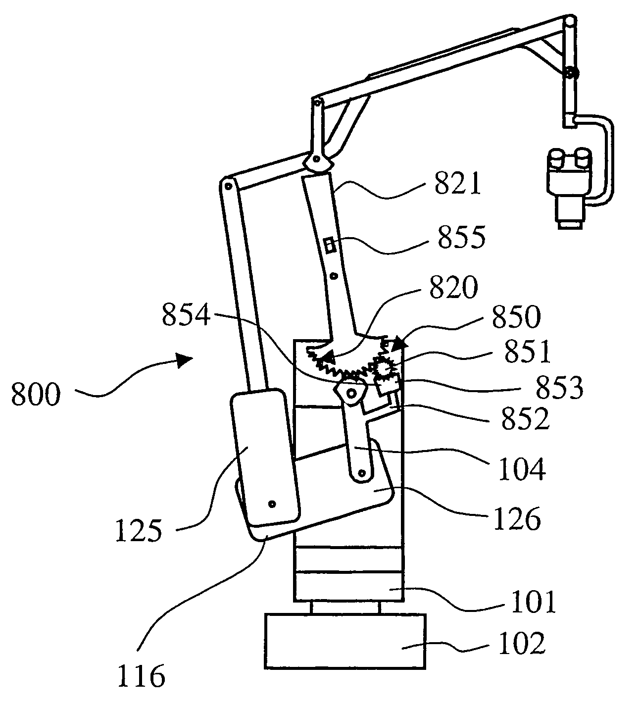
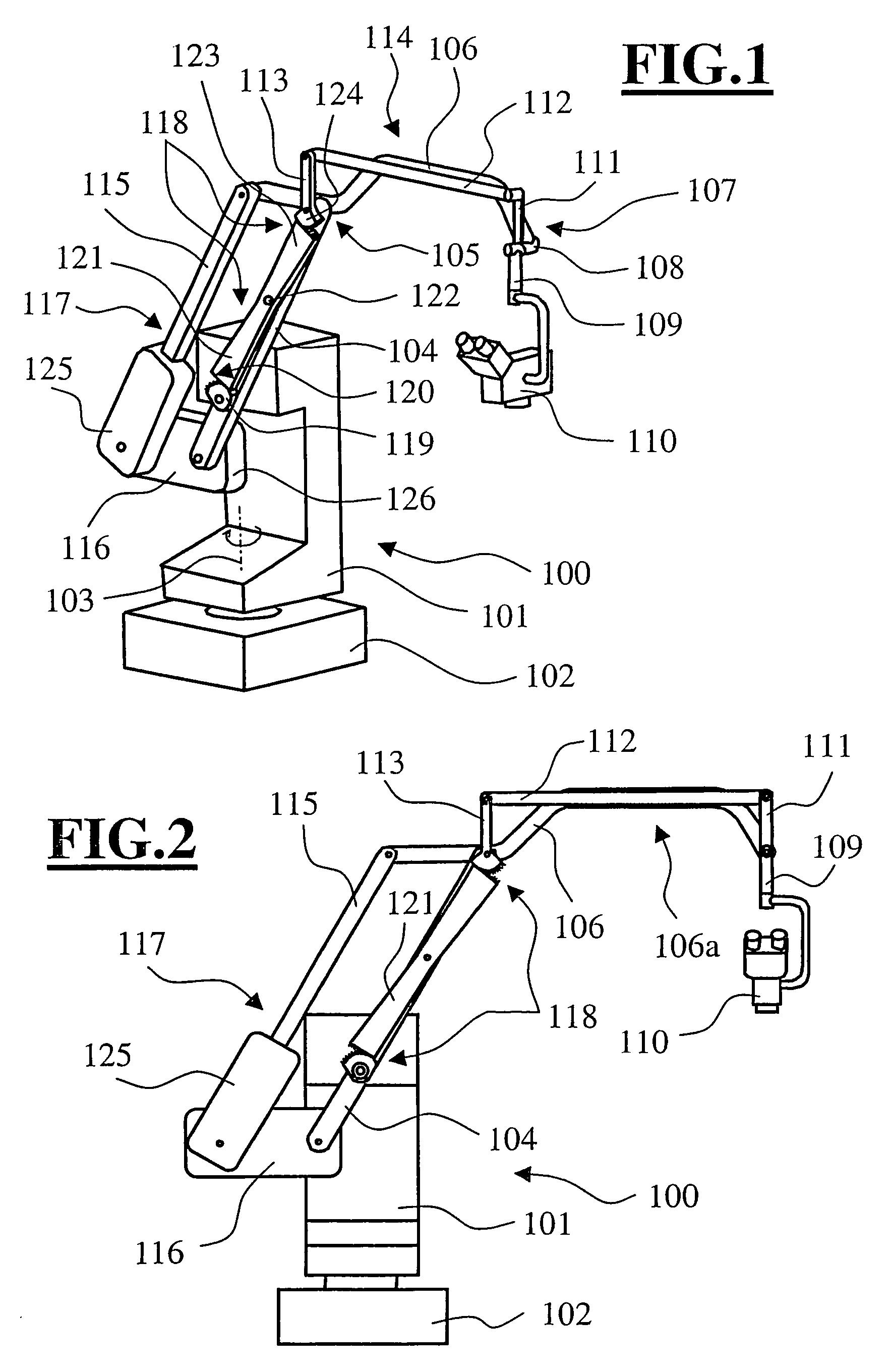
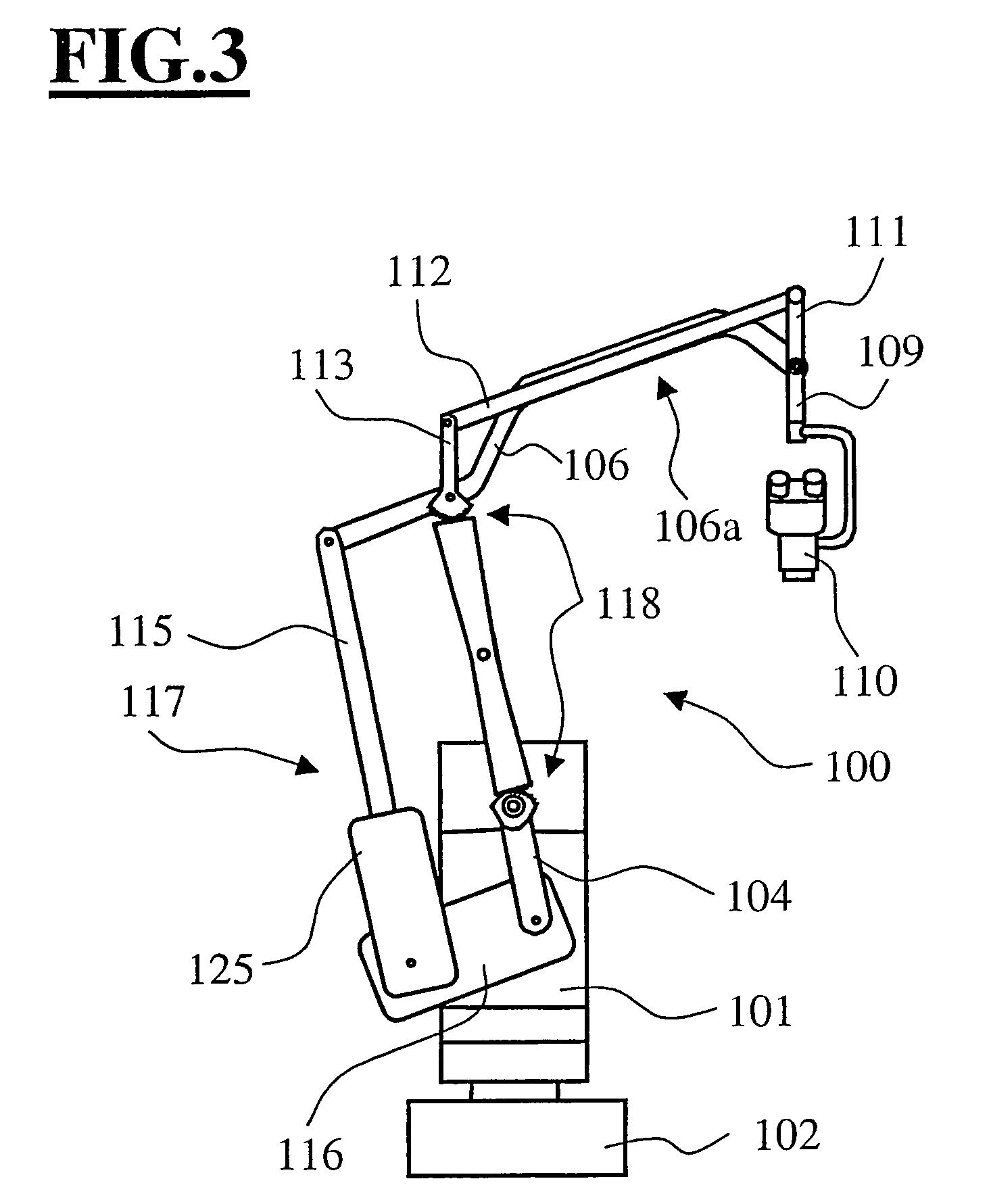
[0027]FIG. 1 shows a stand arrangement 100 having a stand console 101 as a holding unit. The holding unit is supported on a stand base 102 by means of a rotational joint and can be moved about a rotational axis 103. A first link 104 is pivotally-movably attached to the stand console 101 by means of a first rotational joint. A second link 106 is supported on this first link 104 by a second rotational joint 105. A take-up unit 109 is held by a rotational joint 108 on a forward end 107 of this second link 106. This take-up unit 109 carries a surgical microscope 110 as medical-optical equipment. The take-up unit 109 includes a front link 111 which forms a first parallel linkage assembly 114 together with a third link 112, a fourth link 113 and the second link 106. The second link 106 is configured so as to be extended on the end facing away from the take-up unit 109. The second link 106 forms a second parallel linkage assembly 117 together with a sixth link element 115 and a seventh lin...


PUM


Abstract

The invention relates to a stand arrangement (100) for a medical-optical instrument. The stand arrangement includes a first link (104) which is pivotally supported on a holding unit (101) by a first rotational joint. The stand arrangement (100) further includes a second link (106) which is rotatably connected to the first link (104) via a second rotational joint (105). A take-up unit (109) for medical-optical equipment is held in a forward section (107, 108) of the second link (106) by a third rotational joint. The take-up unit (109) includes a front link (111) which, in turn, is connected via a third link (112) and a fourth link (113) to the second rotational joint (105). The holding unit (101) and the fourth link (113) are coupled with the aid of a toothed gear unit (118) in such a manner that the orientation of the front link (111) does not change with the movement of the first link (104).

Description

CROSS REFERENCE TO RELATED APPLICATION[0001]This application claims priority of German patent application no. 103 10 459.3, filed Mar. 7, 2003, the entire content of which is incorporated herein by reference.FIELD OF THE INVENTION[0002]The invention relates to a stand arrangement for a medical-optical instrument having a first link which is pivotally journalled on a holding unit by a first rotational joint and having a second link which is rotatably connected via a second rotational joint to the first link and which carries a take-up unit for medical-optical equipment in a forward section via a third rotational joint. The take-up unit includes a front link which is connected via a third link and a fourth link to the second rotational joint.BACKGROUND OF THE INVENTION[0003]A stand apparatus of the above kind is disclosed in U.S. Pat. No. 5,528,417. There, a stand apparatus for a medical-optical instrument is described which carries medical-optical equipment on a holding unit by means...

Claims


Application Information

Patent Timeline
Patent Type & Authority Patents(United States)
IPC IPC(8): A61B19/00F16M11/12F16M11/04F16M11/02G02B7/00G02B21/24A61B90/25
CPCA61B19/26F16M11/04F16M11/10F16M11/12F16M11/18F16M11/2064F16M11/2092F16M11/24G02B7/001A61B19/5223F16M2200/044F16M2200/063A61B90/50A61B90/20
Inventor BRENNER, ROLANDABELE, KLAUS
Owner CARL ZEISS SMT GMBH
Learn More