Self-aligned coaxial via capacitors

a coaxial capacitor and capacitor technology, applied in the field of capacitors, can solve the problems of increasing noise in the dc power and ground lines, increasing the size of the surface area of the surface-mounted capacitor, and increasing the requirement for higher capacitance requirements

Inactive Publication Date: 2005-11-08
INTEL CORP
View PDF19 Cites 66 Cited by
  • Summary
  • Abstract
  • Description
  • Claims
  • Application Information

AI Technical Summary

Problems solved by technology

As circuit frequencies exceed several hundred megahertz (MHz), with the associated spectral components exceeding 10 gigahertz (GHz), noise in the DC power and ground lines increasingly becomes a problem.
At increasingly reduced device sizes and packing densities, available real estate for

Method used


Image

  • Self-aligned coaxial via capacitors
  • Self-aligned coaxial via capacitors
  • Self-aligned coaxial via capacitors

Examples


Embodiment Construction

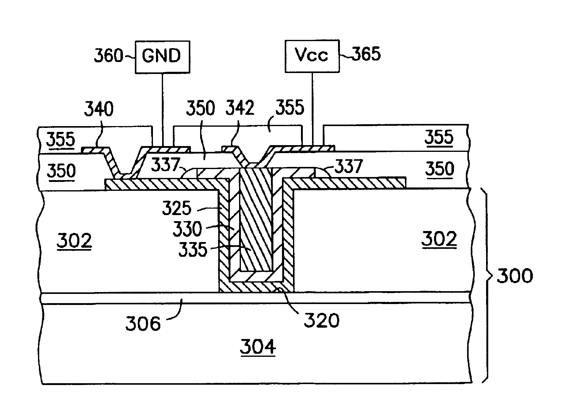
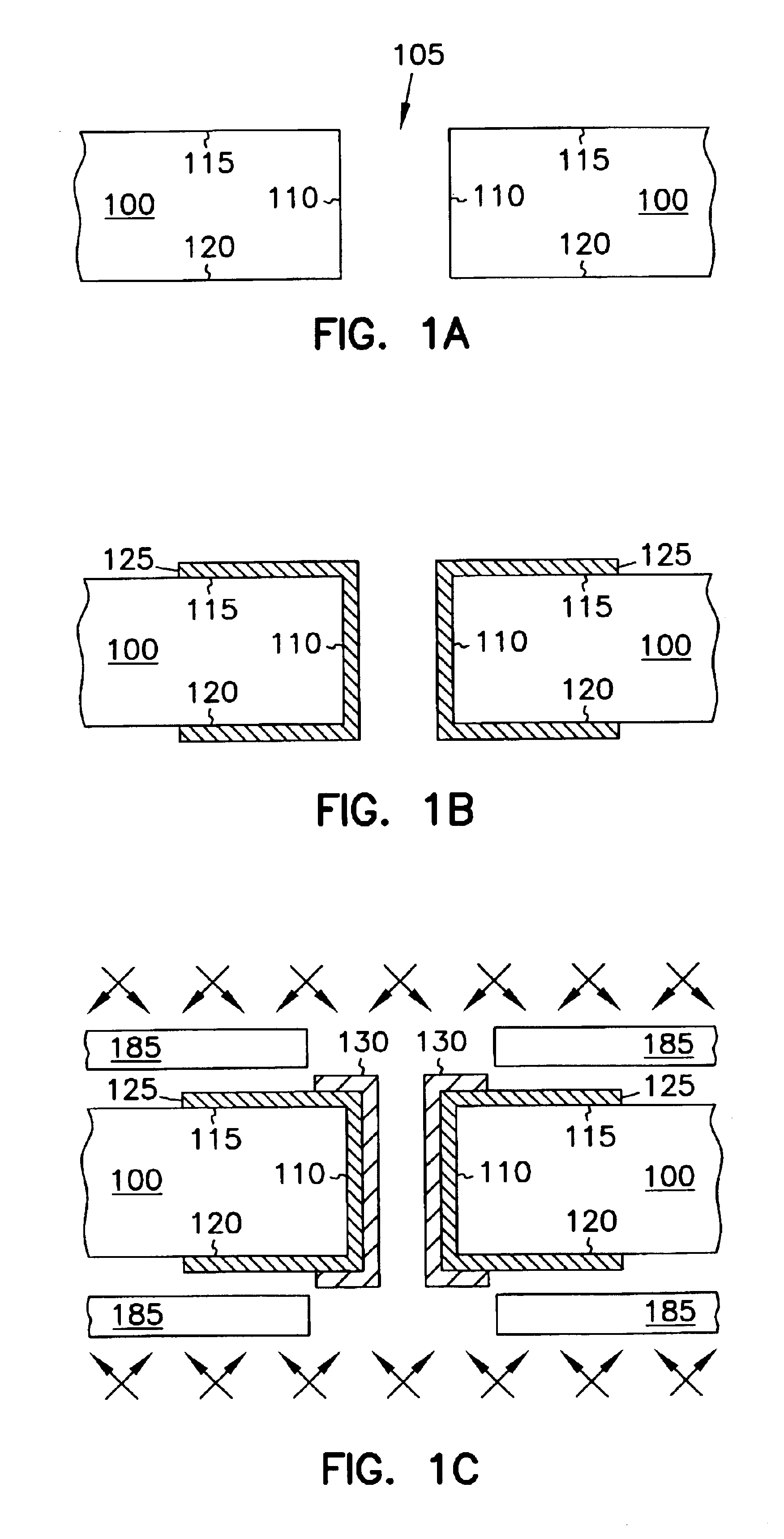
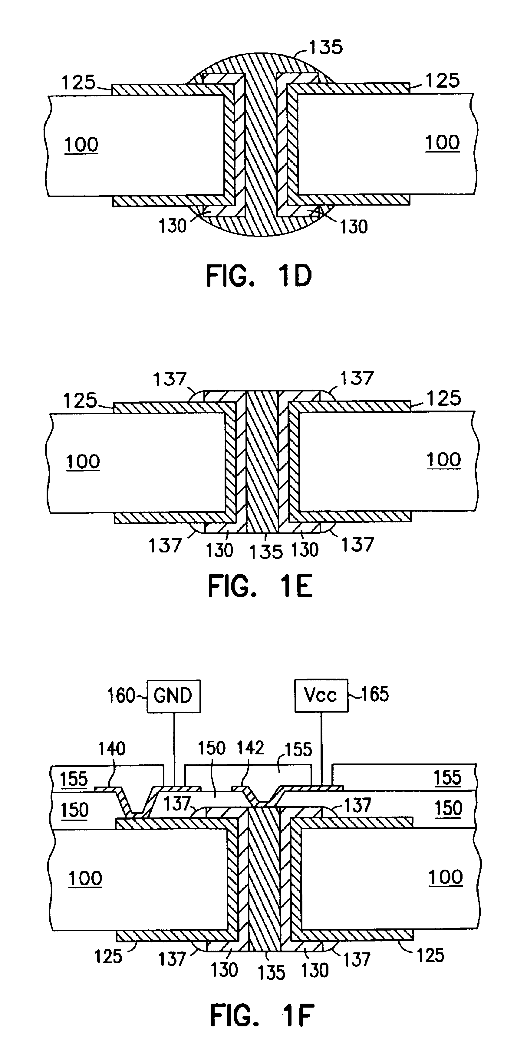
[0016]In the following detailed description, reference is made to the accompanying drawings which form a part hereof, and in which is shown by way of illustration specific embodiments in which the invention may be practiced. These embodiments are described in sufficient detail to enable those skilled in the art to practice the invention, and it is to be understood that other embodiments may be utilized and that structural, logical and electrical changes may be made without departing from the spirit and scope of the invention. The following detailed description is, therefore, not to be taken in a limiting sense, and the scope of the invention is defined only by the appended claims and equivalents thereof. Like numbers in the figures refer to like components, which should be apparent from the context of use.

[0017]The various embodiments will be described in the context of embedded capacitors for microprocessor package applications. One example of a microprocessor package is that of an...


PUM

PropertyMeasurementUnit
Temperatureaaaaaaaaaa
Thicknessaaaaaaaaaa

Abstract

The various embodiments of coaxial capacitors are self-aligned and formed in a via, including blind vias, buried vias and plated through holes. The coaxial capacitors are adapted to utilize the plating of a plated via as a first electrode. The dielectric layer is formed to overlie the first electrode while leaving a portion of the via unfilled. A second electrode is formed in the portion of the via left unfilled by the dielectric layer. Such coaxial capacitors are suited for use in decoupling and power dampening applications to reduce signal and power noise and/or reduce power overshoot and droop in electronic devices. For such applications, it is generally expected that a plurality of coaxial capacitors, often numbering in the thousands, will be coupled in parallel in order to achieve the desired level of capacitance.

Description

[0001]This application is a divisional of U.S. patent application Ser. No. 09 / 474,186, filed Dec. 29, 1999 now U.S. Pat. No 6,565,730, which is incorporated herein by reference.TECHNICAL FIELD OF THE INVENTION[0002]The invention relates generally to capacitors, and more particularly to self-aligned coaxial capacitors formed in vias, apparatus utilizing such capacitors, and methods of their fabrication.BACKGROUND OF THE INVENTION[0003]Electronic circuits, and particularly computer and instrumentation circuits, have in recent years become increasingly powerful and fast. As circuit frequencies exceed several hundred megahertz (MHz), with the associated spectral components exceeding 10 gigahertz (GHz), noise in the DC power and ground lines increasingly becomes a problem. This noise can arise due to inductive and capacitive parasitics, for example, as is well known. To reduce such noise, capacitors known as decoupling capacitors are often used to provide a stable signal or stable supply...

Claims


Application Information

Patent Timeline
IPC IPC(8): H05K1/16H05K3/40H05K3/46H01G2/06H05K1/11
CPCH05K1/162H05K3/4069H05K3/4602Y10T29/43H05K2201/09809H05K2203/0315H05K2201/09509H01L27/04
Inventor CHAKRAVORTY, KISHORE K.DORY, THOMAS S.GARNER, C. MICHAEL
Owner INTEL CORP
Why Eureka
Try Eureka