Multi-system correspondence receiver
a receiver and multi-system technology, applied in the field of multi-system corresponding receivers, can solve the problems of large difference in the time from channel tuning to video image, and large inconvenience for the receiver's user
- Summary
- Abstract
- Description
- Claims
- Application Information
AI Technical Summary
Benefits of technology
Problems solved by technology
Method used
Image
Examples
embodiment 1
(Embodiment 1)
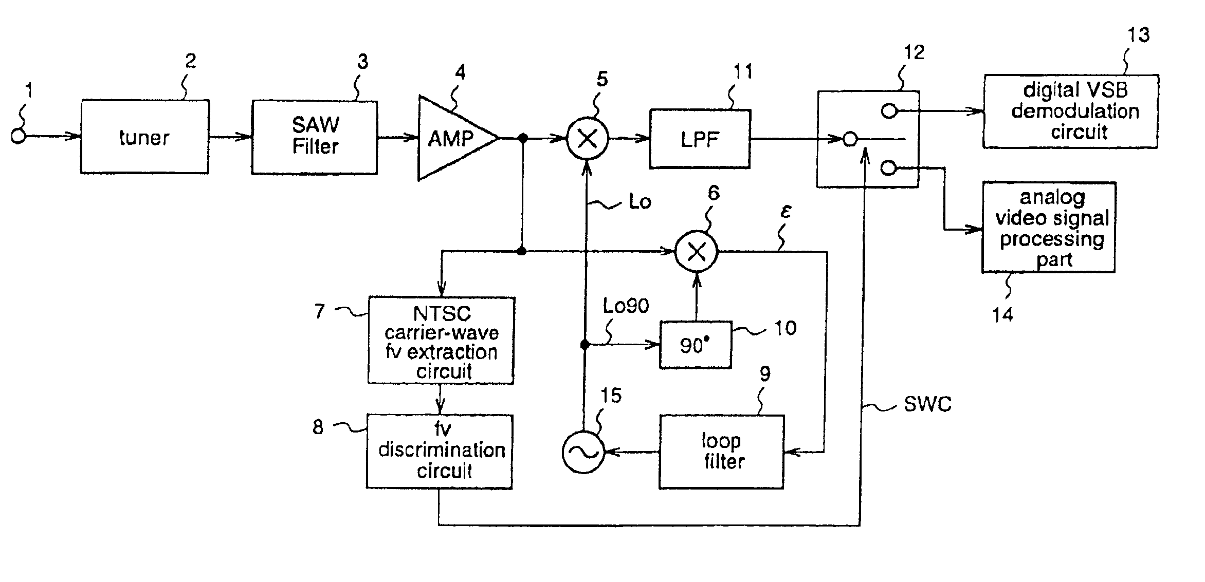
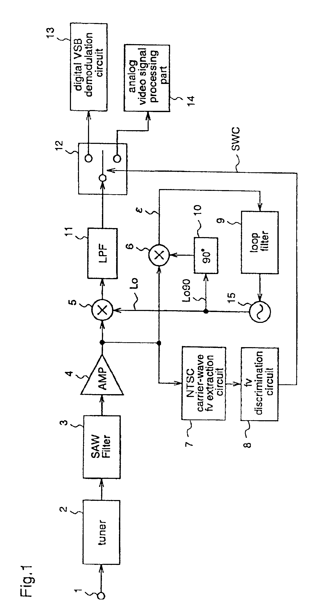
[0064]A first embodiment of the present invention will now be described with reference to FIG. 1.
[0065]FIG. 1 is a block diagram showing a multi-system corresponding receiver corresponding to both of digital ground wave broadcast and NTSC analog broadcast.
[0066]In this multi-system corresponding receiver, there are provided a terminal 1 to which a RF modulation wave is input; a tuner 2 for selecting the channel of received modulation wave; a SAW filter 3 for applying a frequency band limitation to an IF signal at the tuner 2; an AMP 4 for amplifying the IF signal which is output from the SAW filter 3; mixers 5 and 6 for orthogonal wave detecting; a LPF 11 for applying a frequency band limitation to the output signal from the mixer 5; a digital VSB demodulation circuit 13 for performing digital VSB demodulation; an analog video processing circuit 14 for performing analog video processing; a loop filter 9 for applying a frequency band limitation to the output signal from...
embodiment 2
(Embodiment 2)
[0078]A second embodiment corresponding to claims 4 to 6 of the present invention will now be described with reference to FIG. 3.
[0079]FIG. 3 is a block diagram of a multi-system corresponding receiver which corresponds to both of digital QAM modulation system and digital 8VSB modulation system.
[0080]In the figure, there are provided a tuner 2 for selecting the channel of received digital modulation wave; a SAW filter 3 for applying a frequency band limitation to an IF signal at the tuner 2; an AMP 4 for amplifying the IF signal which is output from the SAW filter 3; mixers 5 and 6 for orthogonal wave detecting; a LPF 11 for applying a frequency limitation to the signal output from the mixer 5; a LPF 33 for applying a frequency limitation to the output signal from the mixer 6; a digital VSB demodulation circuit 13 for performing digital VSB demodulation; a QAM demodulation circuit 38 for performing digital QAM demodulation; a Δf detection phase error detection circuit ...
embodiment 3
(Embodiment 3)
[0093]A third embodiment corresponding to claims 7 to 9 of the present invention will now be explained with reference to FIG. 5.
[0094]FIG. 5 is a block diagram of a multi-system corresponding receiver which corresponds to both of digital 8VSB broadcast and NTSC analog broadcast. That is, there are provided two tuners for analog broadcast and digital broadcast, respectively, and a single CPU 57 which controls the whole system.
[0095]In the figure, there are provided a tuner 2 for selecting the channel of received digital modulation wave; a SAW filter 3 for applying a frequency band limitation to the IF signal at the tuner 2; a digital VSB demodulation circuit 13 for performing digital VSB demodulation for the signal output from the SAW filter 3; a TS decoder for decoding a transport data; a digital decoding and signal processing circuit 52 for decoding and video processing the digital data; a terminal 53 for outputting a digitally decoded video signal; a tuner 58 for cha...
PUM
 Abstract
Description
Claims
Application Information
 - R&D
- Intellectual Property
- Life Sciences
- Materials
- Tech Scout
- Unparalleled Data Quality
- Higher Quality Content
- 60% Fewer Hallucinations
Browse by: Latest US Patents, China's latest patents, Technical Efficacy Thesaurus, Application Domain, Technology Topic, Popular Technical Reports.
© 2025 PatSnap. All rights reserved.Legal|Privacy policy|Modern Slavery Act Transparency Statement|Sitemap|About US| Contact US: help@patsnap.com


