Lens barrel

Inactive Publication Date: 2005-11-08
ASAHI KOGAKU KOGYO KK
View PDF133 Cites 28 Cited by
  • Summary
  • Abstract
  • Description
  • Claims
  • Application Information

AI Technical Summary

Benefits of technology

[0005]The present invention provides a lens barrel including a rotatable ring which selectively performs the aforementioned first and second operation

Problems solved by technology

In such known photographing lenses, a drive mechanism for driving the rotatable ring and a mechanism for removing backlash in the rotatable ring in an ope

Method used


Image

  • Lens barrel
  • Lens barrel
  • Lens barrel

Examples


Embodiment Construction

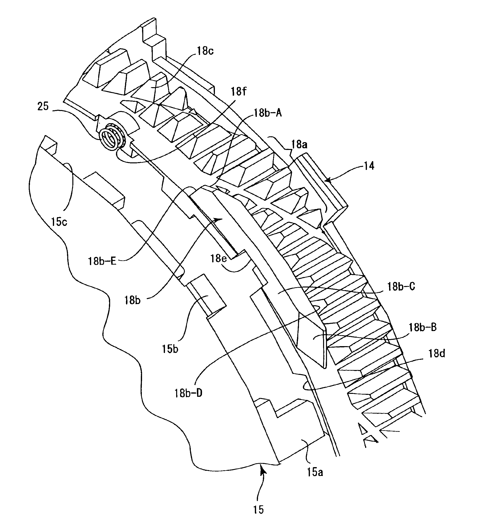
[0186]In some of the drawings, lines of different thicknesses and / or different types of lines are used as the outlines of different elements for the purpose of illustration. Additionally, in some cross sectional drawings, several elements are shown on a common plane, though positioned in different circumferential positions, for the purpose of illustration.

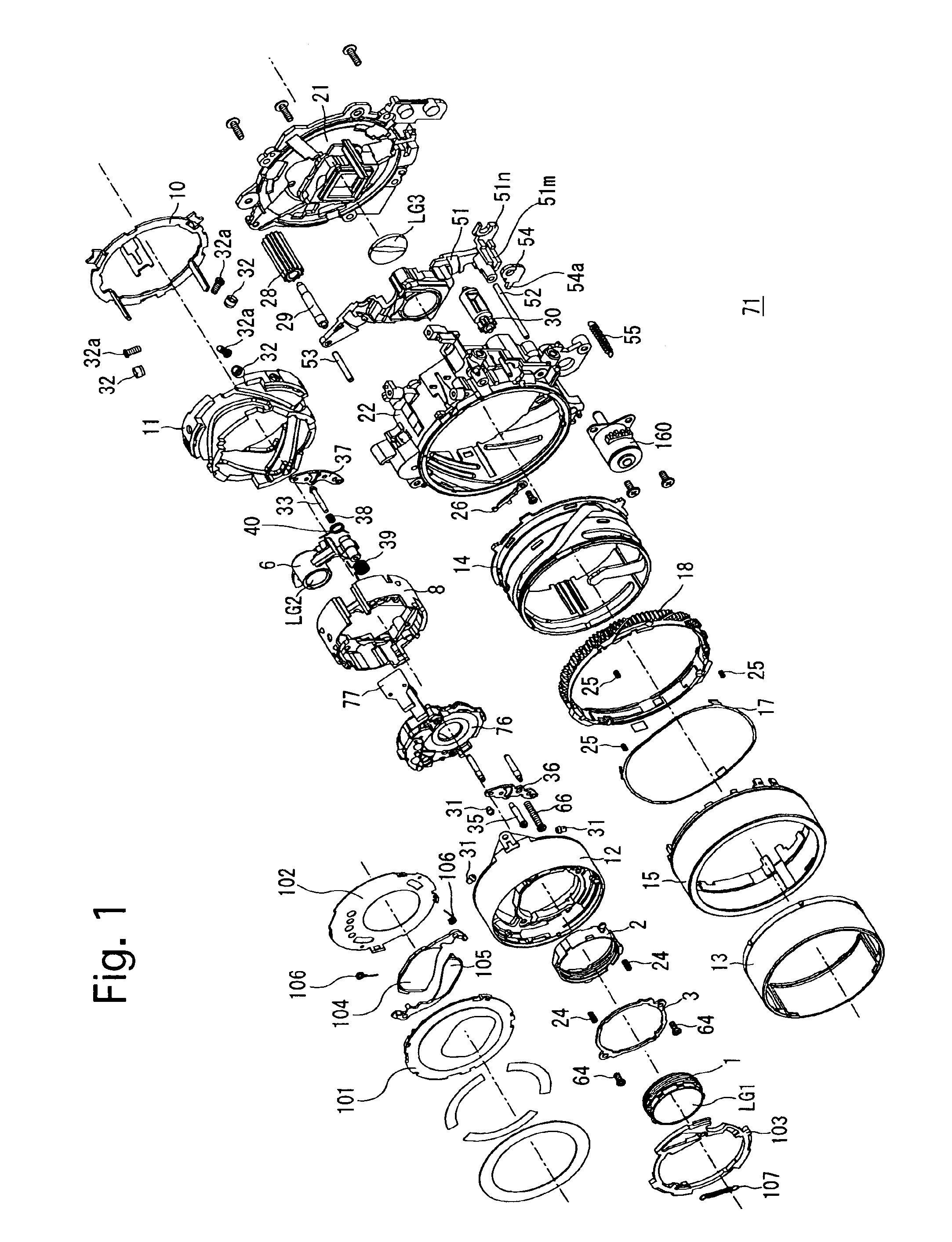
[0187]In FIG. 22, the symbols “(S)”, “(L)”, “(R)” and “(RL)” which are each appended as a suffix to the reference numeral of some elements of a present embodiment of a zoom lens (zoom lens barrel) 71 (see FIGS. 5 through 10) indicate that the element is stationary, the element is solely movable linearly along a lens barrel axis Z0 (see FIGS. 9 and 10) without rotating about the lens barrel axis Z0, the element is rotatable about the lens barrel axis Z0 without moving along the lens barrel axis Z0, and the element is solely movable along the lens barrel axis Z0 while rotating about the lens barrel axis Z0, respectively. Additionally...


PUM


Abstract

A lens barrel includes a non-rotatable annular ring and a circumferential guide groove; a first rotatable ring supported inside the annular ring and including a rotation-guiding projection slidably engaged in the circumferential guide groove; a second rotatable ring which rotates with the first rotatable ring and is only axially movable relative to the first ring, including an engaging projection slidably engaged in the circumferential guide groove with the rotation-guiding projection, wherein the engaging projection is insertable/removable from the circumferential guide groove through the insertable/removable aperture at a first assembling/disassembling angular position; and a coupling ring which is positioned inside the first and second rotatable rings. A coupler provided between the coupling ring and the second rotatable ring is disengaged at a second assembling/disassembling angular position. The first and second assembling/disassembling angular positions are substantially the same.

Description

BACKGROUND OF THE INVENTION[0001]1. Field of the Invention[0002]The present invention relates to a lens barrel such as a photographing (imaging) lens, more specifically to a lens barrel assembling mechanism incorporated in the lens barrel.[0003]2. Description of the Related Art[0004]Photographing lenses (photographing lens barrels) in which a rotatable ring such as a cam ring selectively performs a first operation in which the rotatable ring moves along a photographing optical axis while rotating and a second operation in which the rotatable ring rotates at an axial fixed position on the photographing optical axis without moving therealong are known in the art. In such known photographing lenses, a drive mechanism for driving the rotatable ring and a mechanism for removing backlash in the rotatable ring in an operating state thereof are generally complicated, which makes it difficult to improve the workability of assembling or disassembling the photographing lens.SUMMARY OF THE INVE...

Claims


Application Information

Patent Timeline
IPC IPC(8): G02B15/14G02B7/02G02B7/08G02B7/10G02B7/00
CPCG02B7/022G02B7/026G02B15/14G02B7/102G02B7/08G02B15/143G02B7/04G03B17/14
Inventor NOMURA, HIROSHI
Owner ASAHI KOGAKU KOGYO KK
Why Eureka
Try Eureka