Levelling rod for building construction

a technology for building construction and levelling rods, applied in the direction of mechanical measuring arrangements, machines/engines, instruments, etc., can solve the problems of partial protrusion or cave, uneven floor surface, delay in construction term, etc., and achieve the effect of promoting accurate construction

Inactive Publication Date: 2005-11-15
KIM JIN SUL
View PDF19 Cites 29 Cited by
  • Summary
  • Abstract
  • Description
  • Claims
  • Application Information

AI Technical Summary

Benefits of technology

[0007]Accordingly, an object of the present invention is to provide a levelling rod for building construction, which enables the level of aerated concrete poured onto the floor of buildings to be kept constant in accordance with the level required by a design drawing, and thus promoting an accurate construction.

Problems solved by technology

However, in remote areas from the wall of a building or on the floor of the building, there is no inkline or criteria of indicating the level of mortar to be put on the floor, and therefore the levelling of the entire floor could not but to rely on the skill or dexterity of plasterers.
That is, in conventional constructions using mortar or concrete, levelling the floor of buildings was only dependent on the experience or dexterity of workers, and thus problems were frequently encountered that the surface of the floor was not flat or even, and the floor was partly protruded or caved in.
In this case, an accurate level of mortar on the floor according to a design drawing cannot be obtained, and thus subsequent construction work is required to repair such a defective levelling, which causes the term of construction to be delayed, requires additional building materials such as mortar or concrete, and causes the increase of the costs for materials and the labor costs.
The accurate levelling of the floor of various kinds of buildings has been considerably demanded, but no appropriate devices or instruments have been suggested.
However, as the device does not comprise a cap in its upper part, problems have been encountered that it is difficult to distinguish the device 100 for indicating the concrete level if excessive concrete were poured on the floor, and on the other hand if concrete were insufficiently supplied, the end of a rod of the device is exposed over the floor of slab.

Method used


Image

  • Levelling rod for building construction
  • Levelling rod for building construction
  • Levelling rod for building construction

Examples


Embodiment Construction

[0025]Reference will now be made in detail to preferred embodiments of the present invention with reference to the accompanying drawings.

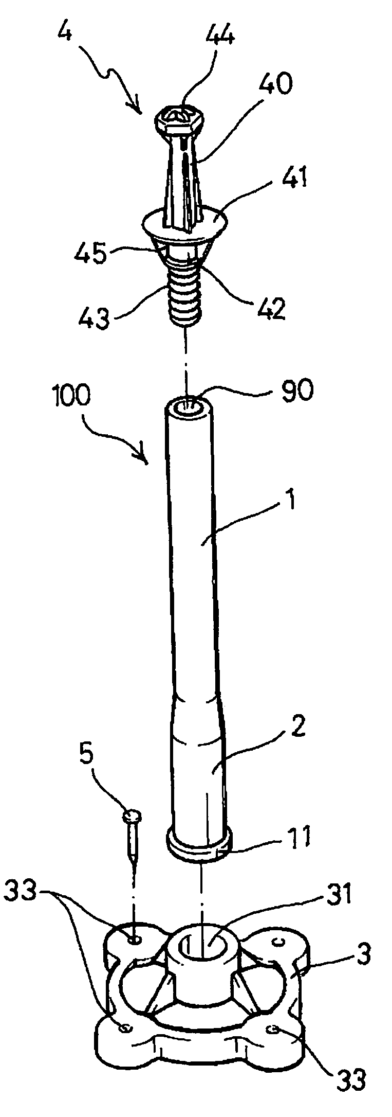
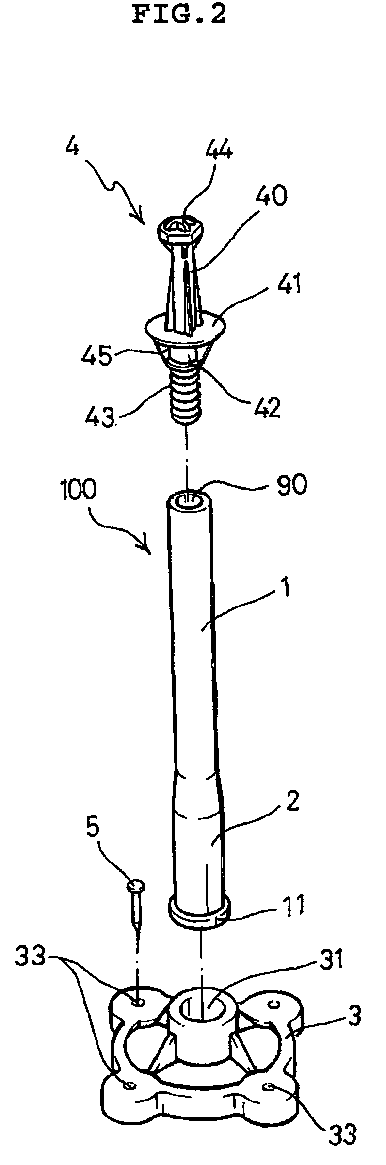
[0026]FIGS. 2 and 3 show an embodiment of a levelling rod 100 used to maintain the level of mortar poured onto the floor of a building constant. The levelling rod 100 comprises a rod for plaster work 1, a fixing member 3 and a cap 4.

[0027]In this embodiment, the rod for plaster work 1 includes a hollow 90 therethrough and a fixing flange 11 formed at a lower end.

[0028]Preferably, the rod for plaster work 1 is made of flexible rubber, and it is tapered in the middle part for the improvement of stability or the force of restitution.

[0029]This is because a hose for supplying mortar is heavy and moves in various directions due to the pressure for pouring mortar on the floor. That is, the rod 1 can restitute to its original position and shape even after the impact or pressure is imposed on its part by the heavy and mobile hose for the supply of mortar, ...


PUM


Abstract

A leveling device for leveling floor pavement layers comprises a rod (1) having a hollow (90) therethrough and a fixing flange (11) for fitting with a fixing member at a lower end, a fixing member (3) including an aperture (31) in the center thereof to be releasably coupled with the rod (1), fixing holes (33) on the outer periphery thereof, a finger stop (310) formed at an end of the aperture (31) to be fitted with the fixing flange (11) of the rod (1) and a cap (4) releasably coupled with the hollow (90) of the rod (1).

Description

TECHNICAL FIELD[0001]The present invention relates to a levelling rod for building construction, especially to a gauge rod for levelling the floor of a building. More specifically, the present invention relates to a rod for levelling the floor of houses or buildings in plastering mortar thereon, thus promoting an accurate construction and reducing the cost and time for construction.BACKGROUND ART[0002]Conventionally, in the finishing construction of plastering mortar on various kinds of buildings such as houses, commercial buildings or underground parking lots, plasterers draw an inkline on the wall of a building and plaster mortar below the inkline along the wall.[0003]However, in remote areas from the wall of a building or on the floor of the building, there is no inkline or criteria of indicating the level of mortar to be put on the floor, and therefore the levelling of the entire floor could not but to rely on the skill or dexterity of plasterers. That is, in conventional constr...

Claims


Application Information

Patent Timeline
Patent Type & Authority Patents(United States)
IPC IPC(8): E04G21/10E04F21/04E04F21/02E04F21/00
CPCE04F21/04E04G21/10E04F21/00
Inventor KIM, JIN SUL
Owner KIM JIN SUL
Why Eureka
Try Eureka