Shock-absorbing system for fastener driving tools

a technology of shock absorption and fastener, which is applied in the direction of portable power-driven tools, manufacturing tools, drilling machines, etc., can solve the problems of significant impact force, significant load applied, and breakage of the various parts of the tool, so as to reduce the stress on the tool member and reduce the impact force

Active Publication Date: 2005-11-15
ILLINOIS TOOL WORKS INC
View PDF10 Cites 34 Cited by
  • Summary
  • Abstract
  • Description
  • Claims
  • Application Information

AI Technical Summary

Benefits of technology

[0010]The above-listed needs are met or exceeded by the present shock-absorbing system for a fastener tool. A main feature of the present system is that the point of contact between the valve sleeve / probe assembly and the cylinder body has been moved away from the conventional location at the lower portion of the cylinder body to an upper part of the cylinder body. Additionally, the system includes a shock-absorbing member for dampening the impact forces and shock transferred from the probe assembly to the cylinder body. The shock-absorbing element is preferably located between upper ends of the arms of the probe assembly and a tab from the cylinder body to reduce the stress on the tool members as the probe assembly returns from the fastener-driving position. It has been found that the current application results in a seven-fold reduction on impact forces generated through combustion. Another feature of the present system is that a pair of valve sleeve return springs used in conventional combustion tools of this type has been replaced by a single spring generally centrally located on an upper probe of the probe assembly.
[0011]More specifically, a combustion chamber assembly for use in a combustion-powered fastener driving tool, includes a cylinder body, a reciprocating probe assembly slidably disposed relative to the cylinder body between a first, extended position and a second, retracted position, and at least one shock-absorbing member operationally associated with at least one of the cylinder body and the probe assembly for reducing shock load generated by the tool during combustion and transmitted between the probe assembly and the cylinder body. The probe assembly includes an upper probe including at least one arm portion configured for sliding relationship relative to the cylinder body and having an upper end, the at least one shock-absorbing element disposed between the upper end and a corresponding element of the cylinder body for transmitting loads from the probe assembly to the cylinder body; wherein the at least one shock-absorbing member is configured for reducing load forces generated in a combustion chamber of the assembly upon the probe assembly reaching the second position, and being configured to have sufficient rigidity to limit the travel of the probe assembly relative to the cylinder body and also sufficient resilience for absorbing shock forces generated by the tool in the second position. In another embodiment, a single spring disposed between the probe assembly and the cylinder body is configured for biasing the probe assembly into the first position.

Problems solved by technology

One disadvantage of conventional combustion tool assemblies is that, as the tool is operated, significant loads are applied to the workpiece contacting element and transmitted throughout the tool assembly.
In particular, as the piston and attached driver blade drive the fastener and reach the bottom of the piston stroke, significant impact forces are generated.
As such, as combustion tools increase in power, the higher loads can lead to breakage of the various parts of the tool, especially the above-discussed contact points between the probe assembly and lower portion of the valve sleeve.
Such repeated impacts have in some cases reduced tool operation life due to premature breakage of components.
Another disadvantage of conventional combustion tool assemblies with higher-powered combustion is that a high driving velocity of the piston can also lead to a higher return velocity of the piston after driving the fastener into the workpiece.
The shock from abruptly stopping the piston at the top of the cylinder, as the upper probe assembly contacts the stop tabs on the cylinder or valve sleeve, can cause the piston to bounce back down the cylinder away from the proper firing position.
A movement away from the proper firing position can unintentionally increase the volume of the combustion chamber and lead to misfires of the tool.

Method used


Image

  • Shock-absorbing system for fastener driving tools
  • Shock-absorbing system for fastener driving tools
  • Shock-absorbing system for fastener driving tools

Examples


Embodiment Construction

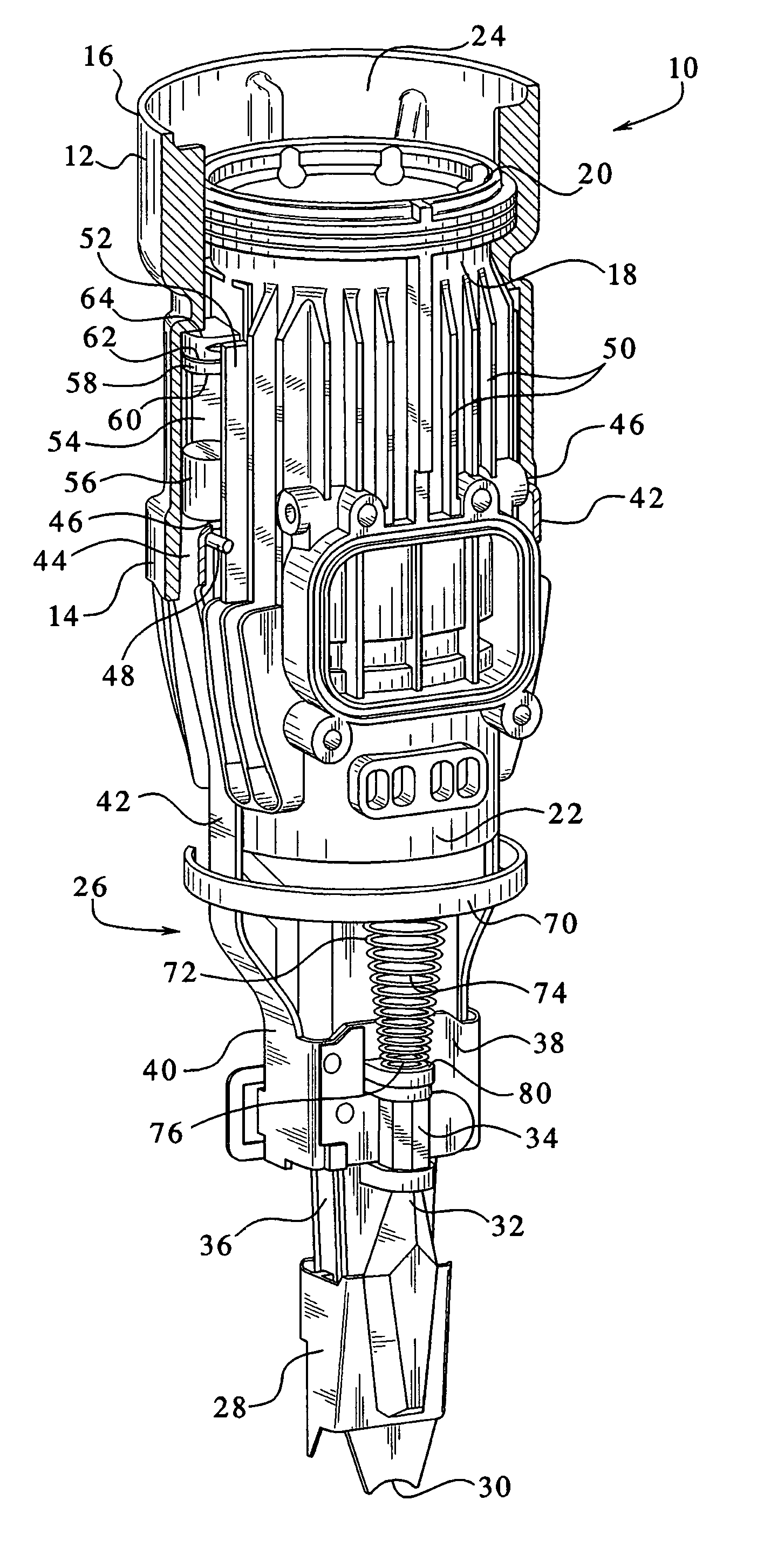
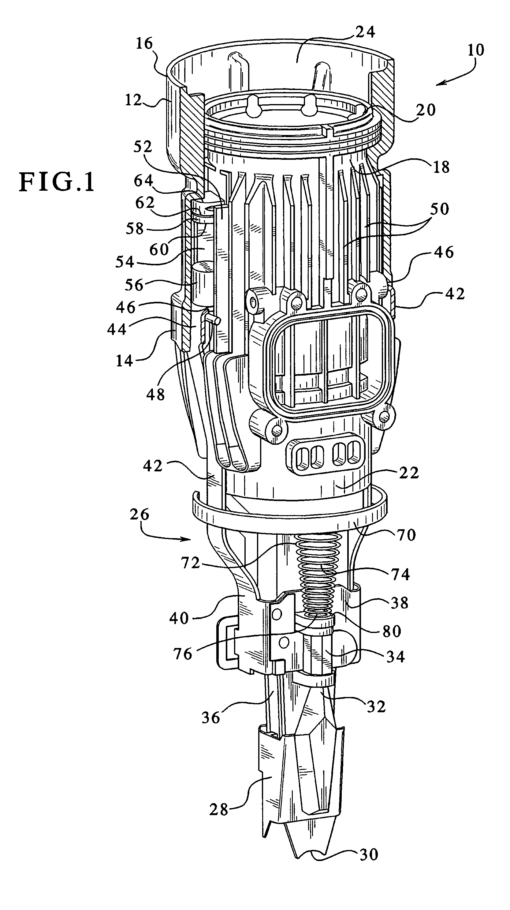
[0015]Referring now to FIG. 1, a combustion chamber assembly incorporating the features of the present shock-absorbing system is generally designated 10 and is intended for use in a combustion-powered tool, especially the type used for driving fasteners. A combustion-powered tool of the type suitable for incorporating the present system is described in detail in the patents incorporated by reference and referred to above. As is known in the art, the combustion chamber assembly 10 includes a valve sleeve 12 which is preferably generally cylindrical in shape. Included on the valve sleeve 12 are a lower end 14 and an upper end 16. As is known in the combustion-tool art, the valve sleeve 12 is slidably engaged upon a generally cylindrical cylinder body 18. An upper end 20 of the cylinder body 18 generally corresponds to the upper end 16 of the valve sleeve 12, and a lower cylinder body end 22 extends below the lower end 14 of the valve sleeve 12. The cylinder body 18 defines a longitudi...


PUM

PropertyMeasurementUnit
speedaaaaaaaaaa
speedaaaaaaaaaa
rigidityaaaaaaaaaa

Abstract

A combustion chamber assembly for use in a combustion-powered fastener driving tool, includes a cylinder body, a reciprocating probe assembly slidably disposed relative to the cylinder body between a first, extended position and a second, retracted position, and at least one shock-absorbing member operationally associated with at least one of the cylinder body and the probe assembly for reducing shock load generated by the tool during combustion and transmitted between the probe assembly and the cylinder body. In another embodiment, a single spring disposed between the probe assembly and the cylinder body is configured for biasing the probe assembly into the first position.

Description

BACKGROUND OF THE INVENTION[0001]The present invention relates to improvements in combustion tools, such as the type used for driving fasteners into work pieces. More specifically, the present invention relates to high-powered combustion tools.[0002]A suitable combustion-powered tool assembly is described in commonly assigned patents to Nikolich U.S. Pat. No. 5,197,646, and U.S. Pat. Nos. 32,452, 4,552,162, 4,483,473, 4,483,474, 4,403,722, and 5,263,439, which are incorporated by reference. Such fastener-driving tools are available commercially from ITW-Paslode (a division of Illinois Tool Works, Inc.) of Vernon Hills, Ill., under its IMPULSE trademark.[0003]Such tools incorporate a generally pistol-shaped tool housing enclosing a small internal combustion engine. The engine is powered by a canister of pressurized fuel gas, also called a fuel cell. A powerful, battery-powered electronic power distribution unit produces the spark for ignition, and a fan located in the combustion cham...

Claims


Application Information

Patent Timeline
Patent Type & Authority Patents(United States)
IPC IPC(8): B25C1/00B25C1/08
CPCB25C1/08B25F5/006B25C1/00
Inventor SHKOLNIKOV, YURYTAYLOR, WALTER J.
Owner ILLINOIS TOOL WORKS INC
Why Eureka
Try Eureka