
Weld-less driver-side inflator

a driver-side inflator and gas generator technology, which is applied in the direction of pedestrian/occupant safety arrangement, vehicle components, chemistry apparatus and processes, etc., can solve the problems of increasing the cost, manufacturing complexity and weight of vehicles, and the heaviest gas generator or inflator used in many occupant restraint systems, and the welding process typically requires relatively expensive manufacturing equipmen

Inactive Publication Date: 2005-11-15
THE UNITED STATES OF AMERICA AS REPRESENTED BY THE SECRETARY OF THE NAVY +1
View PDF30 Cites 9 Cited by
  • Summary
  • Abstract
  • Description
  • Claims
  • Application Information

AI Technical Summary

Benefits of technology

[0006]It is an object of the present invention to provide an inflator that can be assembled without welding the components together.
[0007]It is an object of the present invention to provide an inflator that is light in weight, uses relatively few components, and is easy to assemble.

Problems solved by technology

These systems have made significant contributions to automobile safety, however, as with the addition of any standard feature, they increase the cost, manufacturing complexity and weight of the vehicles.
In particular, the gas generator or inflator used in many occupant restraint systems tends to be the heaviest, most complex component.
The various welding processes typically require relatively expensive manufacturing equipment, and can require substantial processing time.
Various improvements in the techniques and processes for welding inflator components have been made over the years; however, welding can continue to present challenges.
Trained operators and relatively expensive equipment are often necessary in the welding process, and for performing post-processing inspections, such as X-ray inspection of the individual welds.
In addition, the use of lasers or other welding devices around combustible materials such as the gas generant materials used in inflators presents inherent safety problems.
Cuevas requires the use of relatively expensive, complex magnaforming equipment.
Moreover, Cuevas exhibits a relatively complex design in that a securing ring is used to complete the assembly.

Method used


Image

  • Weld-less driver-side inflator
  • Weld-less driver-side inflator
  • Weld-less driver-side inflator

Examples


Embodiment Construction

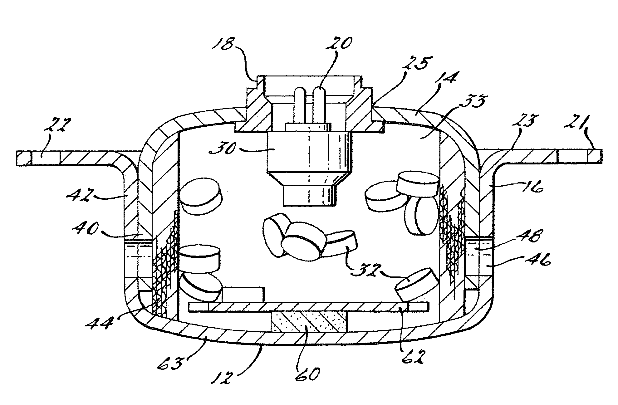
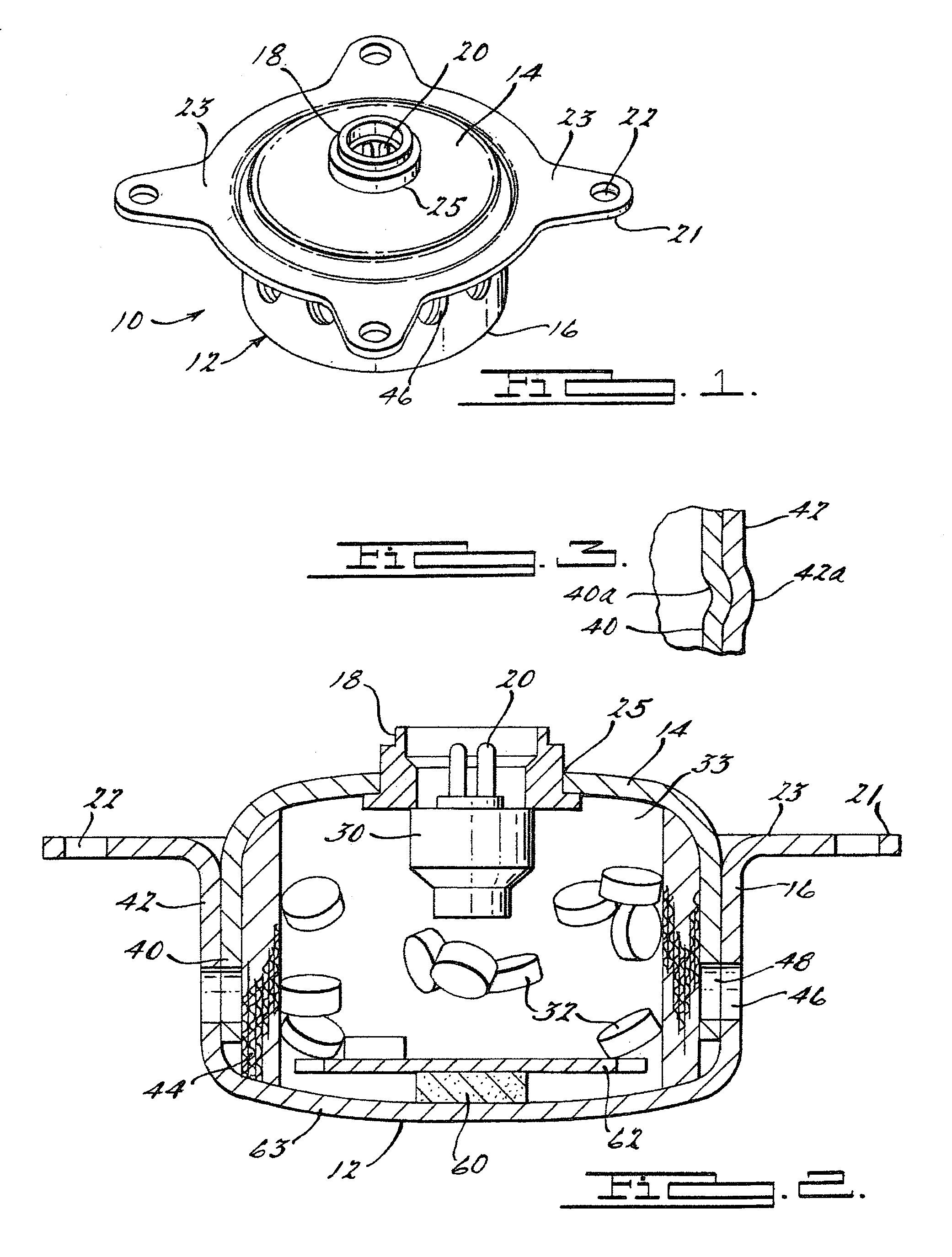
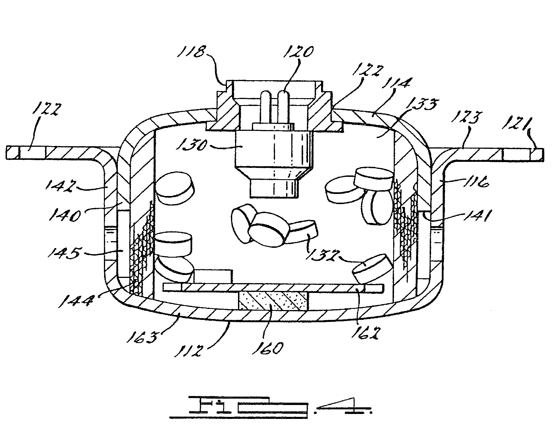
[0015]Referring to FIG. 1, there is shown an inflator or gas generator 10 according to a first preferred constructed embodiment of the present invention. Inflator 10 is preferably a metallic inflator for use in a driver-side inflatable restraint assembly (not shown). In a preferred embodiment, inflator 10 is mounted in a housing at the vehicle steering wheel and cooperates with an inflatable restraint device or airbag, supplying inflation gas thereto for cushioning a vehicle occupant in the event of a crash or sudden deceleration, in a manner well known in the art. Inflator 10 includes an inflator body 12 having a lower body piece or first body cup 16 and an upper body piece or second body cup 14. Lower body piece 16 preferably has a laterally projecting mounting flange 21 with a plurality of lobes 23. Each lobe 23 preferably has a hole 22 therein that receives a mounting member or fastener (not shown), for securing inflator 10 to the steering wheel, airbag housing or related compon...


PUM


Abstract

An inflator (10) is provided for supplying gas to a vehicle airbag from the combustion of pyrotechnic materials. The inflator (10) has a two-piece inflator body (12) held together by crimping the body components, rather than welding. An igniter assembly (18) is positioned in a bore (22) in an upper piece (14) of the inflator body and is held in place with a press-fit interface and an adhesive seal. The upper piece (14) of the inflator body is rounded, increasing its strength, and fits partially into the lower piece (16). A booster tube is unnecessary, making the inflator lighter in weight and increasing available volume for propellant.

Description

[0001]This Application Claims The Benefit Of The Filing Date Of U.S. Provisional Application Ser. No. 60 / 367,825, Filed Mar. 27, 2002, And Incorporated Herein By Reference In Its EntiretyTECHNICAL FIELD[0002]The present invention relates generally to gas generators for vehicle inflatable restraint devices, and more particularly to such a device wherein the gas generator is manufactured without welding.BACKGROUND OF THE INVENTION[0003]Inflatable restraint systems or “airbag” systems have become a standard feature in many new vehicles. These systems have made significant contributions to automobile safety, however, as with the addition of any standard feature, they increase the cost, manufacturing complexity and weight of the vehicles. Technological advances addressing these concerns are typically welcomed by the industry. In particular, the gas generator or inflator used in many occupant restraint systems tends to be the heaviest, most complex component. Thus, trimming weight and ass...

Claims


Application Information

Patent Timeline
IPC IPC(8): B60R21/26B01J7/00
CPCB60R21/2644B60R2021/26076
Inventor BLACKBURN, JEFFERY S.EDWARDS, II, PAUL C.FRITH, SIMON A. M.
Owner THE UNITED STATES OF AMERICA AS REPRESENTED BY THE SECRETARY OF THE NAVY
Learn More