System and method for stabilizing the human spine with a bone plate

a technology of bone plate and fixation system, which is applied in the field of spinal fixation system, can solve the problems of risky fixation of spinal plate to cervical portion of spine, risky movement of uni-cortical fasteners, and inability to maintain the position of uni-cortical fasteners, so as to inhibit the backout of the fastener and strong connection

Inactive Publication Date: 2005-11-15
ZIMMER SPINE INC
View PDF263 Cites 375 Cited by
  • Summary
  • Abstract
  • Description
  • Claims
  • Application Information

AI Technical Summary

Benefits of technology

[0012]The end holes extend from an upper surface to a lower surface of the plate. The end holes may be disposed in pairs at opposite ends of the plate. Each end hole receives at least a portion of a head of a fastener. Herein, “fastener” means any elongated member, threaded or non-threaded, which is securable within a bone. Fasteners include, but are not limited to screws, nails, rivets, trocars, pins, and barbs. The fastener may be a bone screw. A fastener may have a fastener head. The fastener head typically includes an opening adapted to mate with a tool. The tool allows the insertion of the fastener into a bone. Each end hole may also be spherically contoured to permit the fastener to be “obliquely angulated” relative to the plate. Herein, “obliquely angulated” means that the fastener may be positioned throughout a wide range of angles relative to an axis that is perpendicular to the plate. Obliquely angulating a fastener into a bone may reduce the risk of backout of the fastener.
[0025]Using a locking mechanism between the fastener head and the ring may result in a strong connection between the fastener and the plate. Even if the shank of a fastener loosens within the bone, the fastener head will tend to remain within the hole of the plate so as not to protrude from the plate into surrounding body tissue. Allowing some axial freedom of movement for the fastener head in the ring may allow the fastener to back out slightly during an adjustment period after installation of the spinal fixation system.

Problems solved by technology

Spinal plate fixation to the cervical portion of the spine may be risky because complications during surgery may cause injury to vital organs, such as the brain stem or the spinal cord.
Bi-cortical fasteners are intended to breach the distal cortex for maximum anchorage into the bone; however, this placement of the fasteners may place distal soft tissue structures at risk.
Unfortunately, uni-cortical fasteners may move from their desired positions because of the soft texture of the bone marrow.
In fact, the portion of the bone surrounding such fasteners may fail to maintain the fasteners in their proper positions.
The result is backout of the fastener.
Backout of the fastener is particularly problematic when two fasteners are implanted perpendicular to the plate.
When the fasteners are placed in such a manner, backout may occur as a result of bone failure over a region that is the size of the outer diameter of the fastener threads.
Although positioning convergent or divergent fasteners in a bone reduces the risk of backout, backout may still occur.
Backout may damage internal tissue structures and cause complications if the dislocated fastener penetrates the tissue structures.
For example, if backout occurs, the fastener might breach the esophageal wall of the patient.
Such a breach may permit bacterial contamination of surrounding tissues, including critical nerves in and around the spinal cord.
Such a breach could be fatal.
Positioning and inserting a lock fastener within the opening can be difficult due to the small size of the lock fastener.
The surgeon may be unable to hold onto the lock fastener without dropping it.
If a lock fastener falls into the surgical wound, it may be difficult to retrieve.
In some instances, the lock fastener may be unretrievable.

Method used


Image

  • System and method for stabilizing the human spine with a bone plate
  • System and method for stabilizing the human spine with a bone plate
  • System and method for stabilizing the human spine with a bone plate

Examples


Embodiment Construction

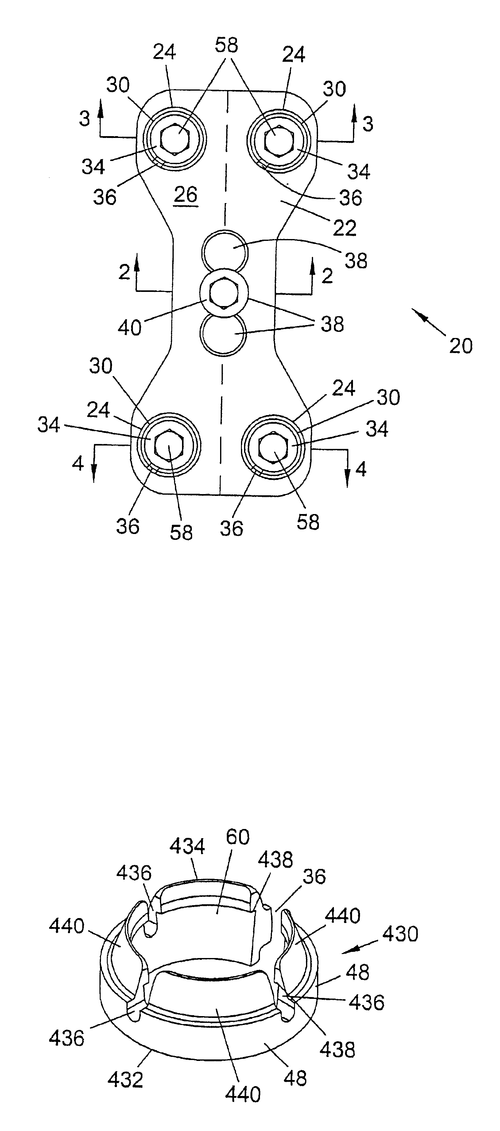
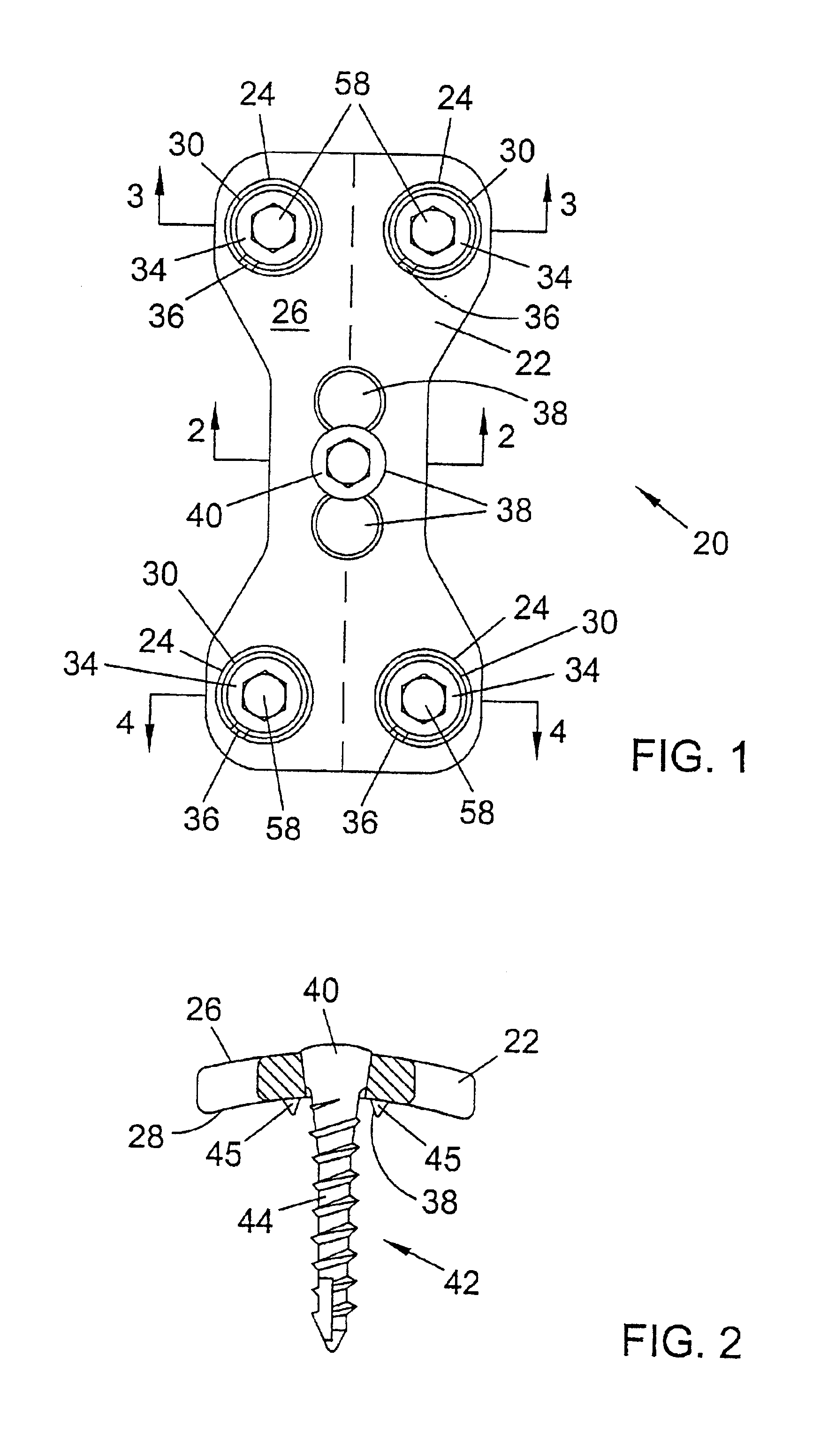
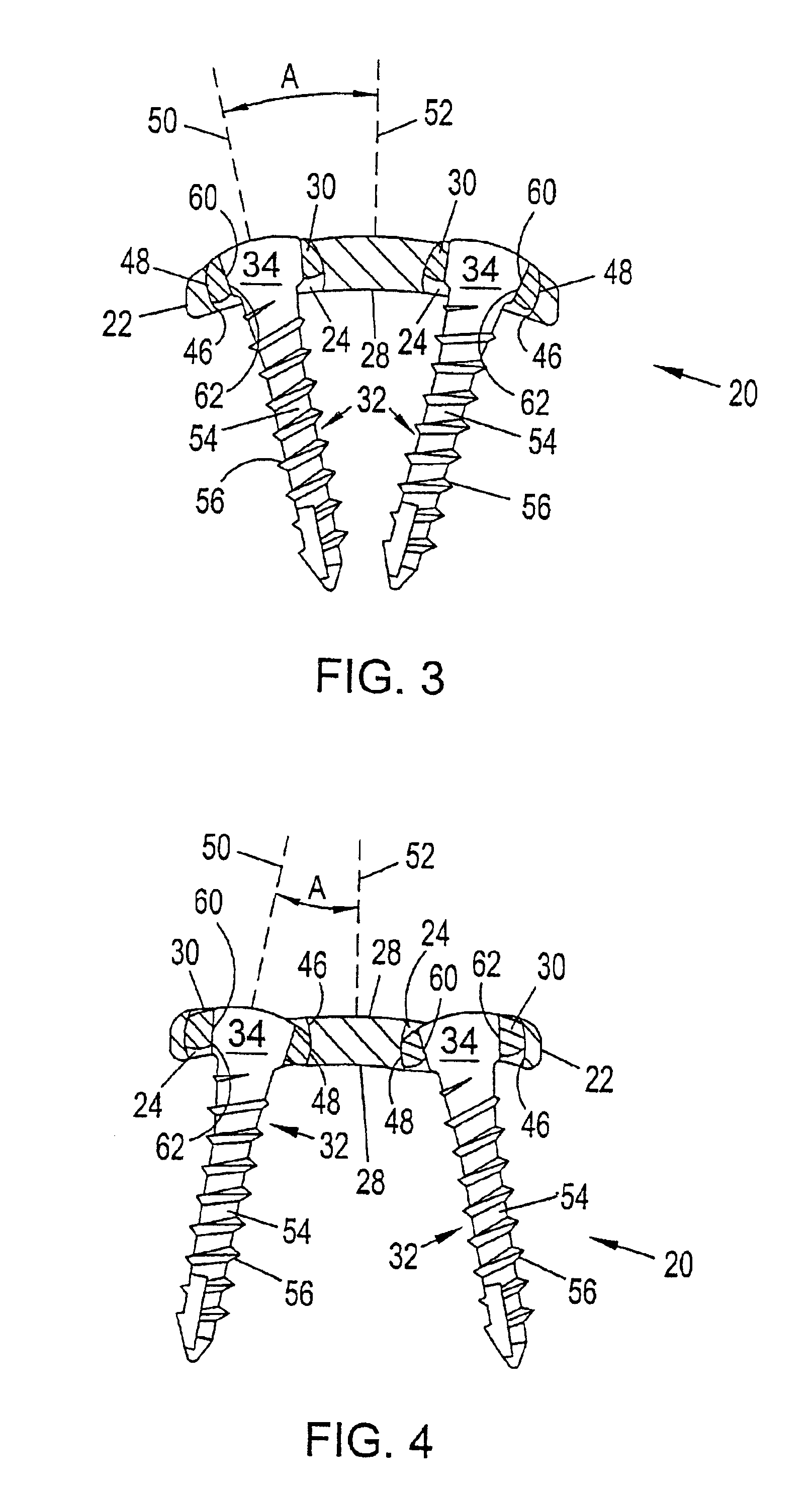
[0054]Referring to the drawings, and particularly to FIG. 1, a spinal plating system is designated generally as 20. The spinal plating system 20 may be used to correct problems in the lumbar and cervical portions of the spine. For example, the spinal plating system 20 may be implanted into the occiput bone that is located at the base of the skull. The spinal plating system 20 may also be installed anterior to the spine. The spinal plating system 20 includes plate 22 that is placed adjacent to a portion of the spine and spans at least two vertebrae. Plate 22 may include four end holes 24, located at corners of the plate. End holes 24 pass vertically through plate 22 such that the holes extend from an upper surface 26 to a lower surface 28 of the plate as depicted in FIG. 2. End holes 24 are configured to receive rings 30. Fasteners 32 fit within the rings 30. Herein, “fastener” means any elongated member, threaded or non-threaded, which is securable within a bone. Fasteners include, ...


PUM


Abstract

A spinal plate system and method for fixation of the human spine is provided. In an embodiment, the spinal fixation system includes a plate, a coupling member, a locking system for substantially locking the coupling member in a desired position, and an anchoring system to secure the coupling member in the locking system. The plate may have a hole that allows the coupling member to couple the plate with a bone. At least a portion of the coupling member may swivel in the hole so that a bottom end of the member may extend at a plurality of angles substantially oblique to the plate. The locking system may lock the coupling member in desired positions relative to the plate. The anchoring system may secure the coupling member in the locking system to inhibit the coupling system from detaching from the locking system when stressed. An assembly tool may be used to engage and disengage the anchoring system during the installation or removal of the spinal fixation system.

Description

[0001]This patent is a continuation of application Ser. No. 09 / 479,458 filed Jan. 6, 2000, now U.S. Pat, No. 6,331,179.BACKGROUND OF THE INVENTION[0002]1. Field of the Invention[0003]The present invention generally relates to spinal fixation systems and the like. The present invention also generally relates to a spinal plate system that includes a mechanism for fixably attaching heads of fasteners to a spinal plate.[0004]2. Description of the Related Art[0005]The use of spinal fixation plates for correction of spinal deformities and for fusion of vertebrae is well known. Typically, a rigid plate is positioned to span bones or bone segments that need to be immobilized with respect to one another. Bone screws may be used to fasten the plate to the bones. Spinal plating systems are commonly used to correct problems in the lumbar and cervical portions of the spine, and are often installed posterior or anterior to the spine.[0006]Spinal plate fixation to the cervical portion of the spine...

Claims


Application Information

Patent Timeline
Patent Type & Authority Patents(United States)
IPC IPC(8): A61B17/70A61B17/88A61B17/68A61B17/80A61B17/58
CPCA61B17/7059A61B17/8047A61B17/861A61B17/8877A61B17/8894A61B17/8052Y10S606/915
Inventor FREID, JIMLANDRY, MICHAEL E.WAGNER, ERIK J.
Owner ZIMMER SPINE INC
Why Eureka
Try Eureka