Expandable medical device with tapered hinge

a medical device and hinge technology, applied in the field of expandable medical devices, can solve the problems of destructive lumen tissue, difficult to securely crimp the most known stent onto the delivery catheter balloon, and higher rates of restenosis

Inactive Publication Date: 2005-11-15
INNOVATIONAL HLDG LLC
View PDF246 Cites 50 Cited by
  • Summary
  • Abstract
  • Description
  • Claims
  • Application Information

AI Technical Summary

Benefits of technology

[0016]The present invention makes novel use of hinges to provide both the spring force and two degrees-of-freedom motions required for a true self-locking expandable medical device design. In addition to that above the present invention provides a novel expandable medical device that is capable of self-expansion or expansion through the use of a balloon catheter or similar device. Further still, the expandable medical device according to the present invention may be utilized to deliver a beneficial agent to the area adjacent to the expanded medical device.
[0018]In accordance with another aspect of the present invention there is provided an expandable medical device including a cylindrical tube and a plurality of axial slots formed in the cylindrical tube in an arrangement to define a network of elongated struts, wherein each of the elongated struts are radially displaced from adjacent struts, and each elongated strut further includes at least one tooth disposed thereupon. A pawl formed between the elongated struts has a distal end adapted to be received by the tooth. A plurality of hinges formed between the elongated struts allow the cylindrical tube to be expanded from a first diameter to a second diameter by bending of the hinges and engaging the distal end of the pawl with the tooth.
[0019]In accordance with another aspect of the present invention there is provided an expandable medical device including, a cylindrical expandable body of Nitinol and a locking feature for locking the expanded body in an expanded position, wherein the locking mechanism prevents recoil of the expanded body of greater than 5 percent.

Problems solved by technology

Over-expansion is potentially destructive to the lumen tissue and is known to cause higher rates of restenosis.
Large recoil also makes it very difficult to securely crimp most known stents onto delivery catheter balloons.
As a result, slippage of stents on balloons during intralumenal transportation, final positioning, and implantation has been an ongoing problem.
Some materials have intrinsic properties that are beneficial in some aspects of stent design, and undesirable in other aspects.
When incorporated into conventional stent designs, these properties produce stents that have unusually good flexibility, deliverability, conformability and radiopacity, but also unacceptably high recoil and poor radial strength.
A number of such locking stent designs have been proposed for conventional materials like stainless steel, but none has proven workable in practice.
Many of the designs are simply impossible to manufacture on a small scale.
More fundamentally, most of the designs fail to provide the basic mechanical requirements of a ratchet or detent mechanism: 1) two degree-of-freedom differential motion between the engaging elements, and 2) a restoring or spring force between the elements.
It is relatively easy to provide these two elements in larger mechanisms comprised of discrete components, but much more difficult to provide this functionality while cutting all features into a very small, continuous, cylindrical surface.
This high ratio of strut width to thickness, combined with the relatively high strut length and the initial curvature of the stent tubing combine to cause the instability and bucking often seen in this type of stent design.
However, as discussed above non-uniform expansion is even more of a problem when smaller feature widths and thicknesses are involved because manufacturing variations become proportionately more significant.
This concentration of plastic strain without any provision for controlling the level of plastic strain makes the stent highly vulnerable to failure.

Method used


Image

  • Expandable medical device with tapered hinge
  • Expandable medical device with tapered hinge
  • Expandable medical device with tapered hinge

Examples


Embodiment Construction

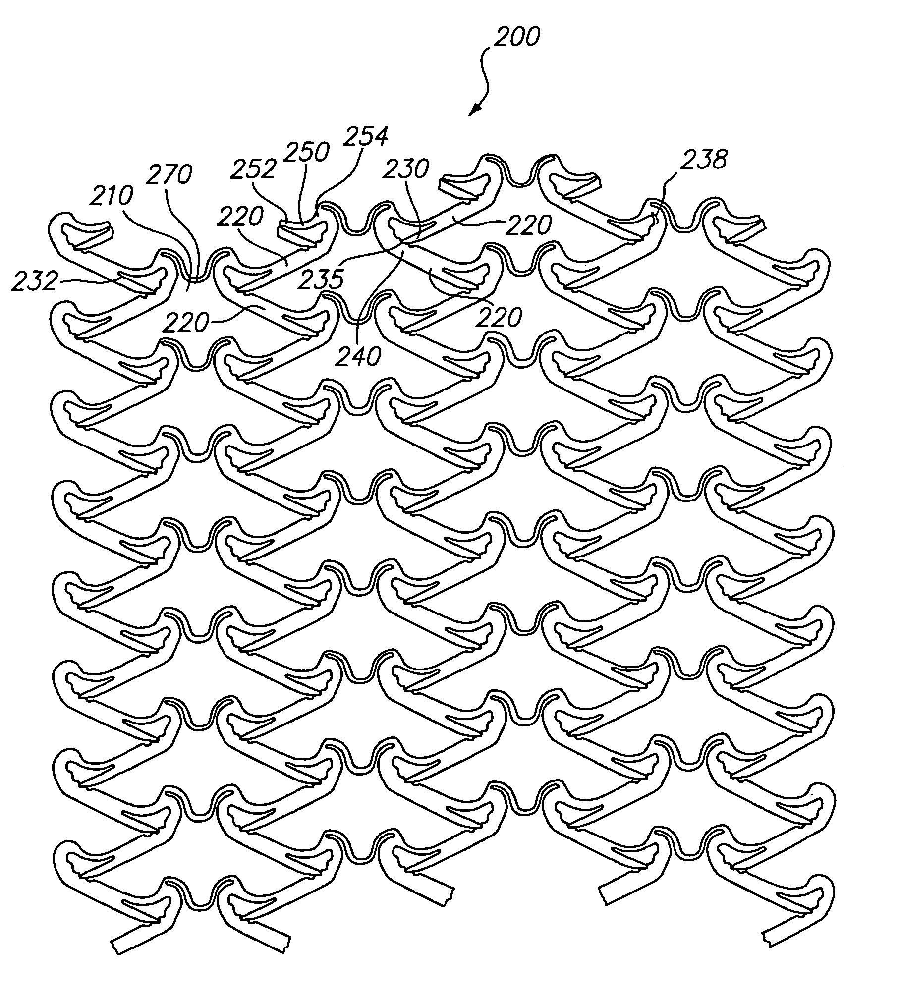
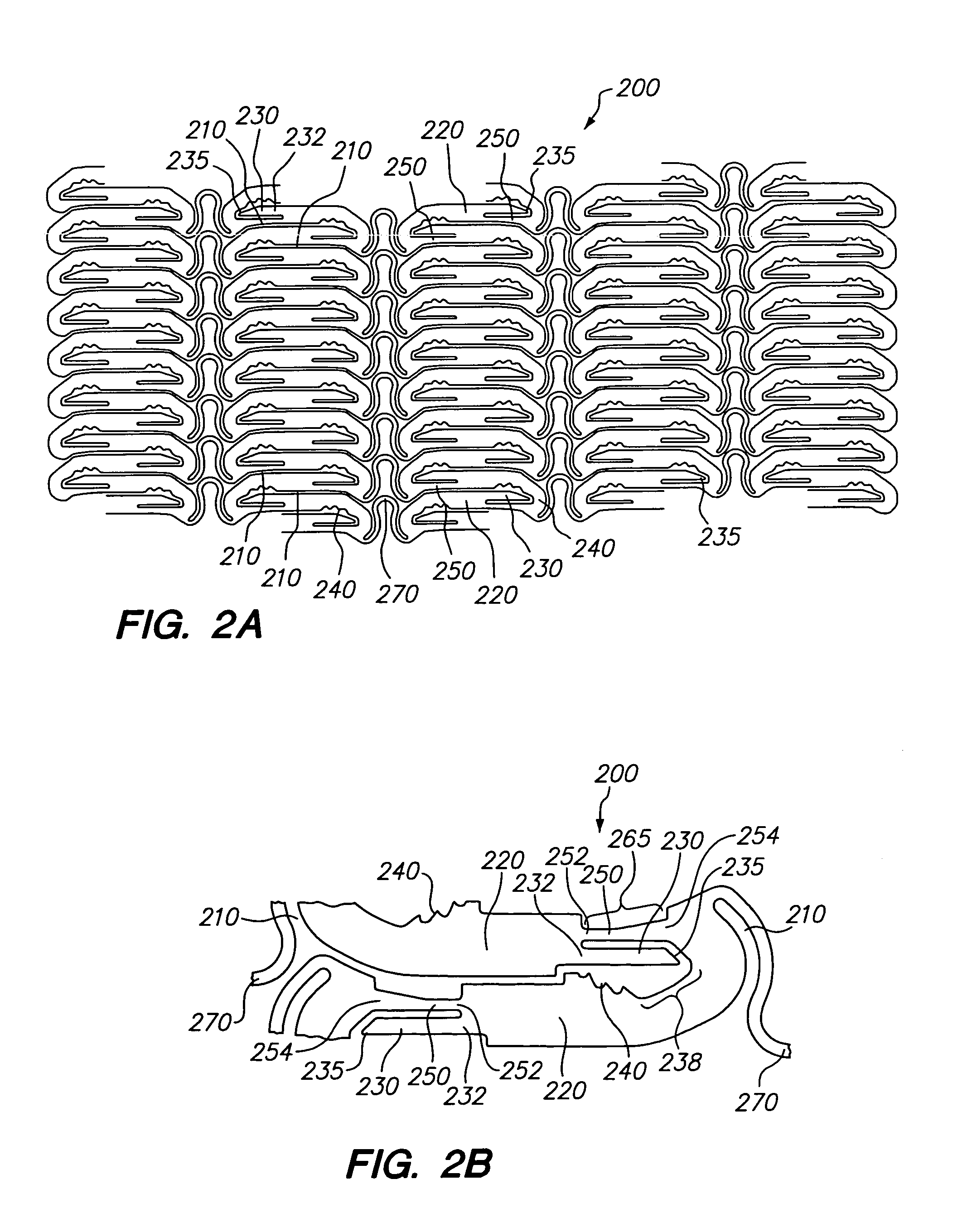
[0033]Referring now to FIGS. 2A and 2B, there is shown a planar view of a representative portion of an unexpanded tissue-supporting medical device 200. The expandable medical device 200 includes a series of axial slots 210 formed in a cylindrical tube (not shown). Each axial slot 210 is displaced radially from the slots in the adjacent rows of slots by approximately 0.010 inches. The plurality of axial slots 210 define a plurality of elongated beams 220. The plurality of elongated beams 220 are interconnected by a hinge 250 disposed at one end and a locking area disposed at the other end. A U-shaped link 270 interconnects adjacent rows of beams 220.

[0034]The elongated beam 220 further includes a pawl 230 having a distal end 235 disposed at one end of the elongated beam 220 and a plurality of teeth 240 disposed at the other end opposite the pawl 230. The elongated beam 220 further includes a hinge 250 adjacent the pawl 230. The hinge 250 further contains a first end 252 and a second ...


PUM


Abstract

According to the present invention there is provided an expandable medical device having, a plurality of elongated beams, the plurality of elongated beams joined together to form a substantially cylindrical device which is expandable from a cylinder having a first diameter to a cylinder having a second diameter. A plurality of hinges connecting the elongated beams have a hinge width, wherein the hinge width is smaller than the beam width. A pawl is disposed adjacent to and substantially parallel to the hinge prior to expansion of the medical device and a plurality of teeth are adapted to receive the pawl. The present invention additionally provides the benefit of limiting the amount of recoil of an expandable device by engaging a locking mechanism, thereby retaining the expanded diameter of the device.

Description

CLAIM OF PRIORITY[0001]The present application claims priority to U.S. Provisional Patent Application Ser. No. 60 / 266,805 filed Feb. 5, 2001, the entirety of which is hereby incorporated by reference.FIELD OF THE INVENTION[0002]This invention relates to expandable medical devices, more particularly to an expandable medical device including a locking mechanism and low recoil after expansion from one diameter to a greater second diameter.SUMMARY OF THE RELATED ART[0003]In the past, permanent or biodegradable devices have been developed for implantation within a body passageway to maintain patency of the passageway. These devices are typically introduced percutaneously, and transported transluminally until positioned at a desired location. These devices are then expanded either mechanically, such as by the expansion of a mandrel or balloon positioned inside the device, or expand themselves by releasing stored energy upon actuation within the body. Once expanded within the lumen, these ...

Claims


Application Information

Patent Timeline
Patent Type & Authority Patents(United States)
IPC IPC(8): A61F2/06A61F2/02A61F2/84A61F2/90
CPCA61F2/91A61F2/915A61F2002/91541A61F2002/91558A61F2002/91591A61F2250/0004
Inventor SHANLEY, JOHN F.
Owner INNOVATIONAL HLDG LLC
Why Eureka
Try Eureka