Frame for electrical and electronic equipment housing cabinets and a frame joining structure

Inactive Publication Date: 2005-11-15
NITTO KOGYO KK
View PDF5 Cites 18 Cited by
  • Summary
  • Abstract
  • Description
  • Claims
  • Application Information

AI Technical Summary

Benefits of technology

[0028]Cost reduction and improvement in outward appearance can be contemplated by using welding to ensure strength and rigidity, and using rivets or the like

Problems solved by technology

(1) Among these conventional structures, one with respective frames of simple square-shaped cross section involves no special problem. However, since recessed portions and waterproof sides are frequently provided on respective frames in view of strength and waterproofness, there has been caused a problem that frame ends are cut in a complex manner and corner members conformed to a configuration of the frame ends are needed.
(2) Hollow frames have an advantage in easiness of ensuring strength. However, in the case where equipment mount holes are formed on the hollow frames, there has been involved a disadvantage in the necessity of using special nuts and mounting of equipments with a special structure because frame interiors are not accessible. On the other hand, open frames without hollow portions make it possible to easily mount equipments without the use of special nuts or the like, but there has been caused a problem that an adequate strength cannot be obtained.
(3) Among conventional vertical frames, one provided with, for example, L-shaped sides involves a problem in the need of large contact forces for sure close contact over an entire surface because a bent surface of the frame abuts against a packing to be large in contact area.
(4) Meanwhile, a frame provided with flat plate-shaped draining sides provides sure sealing with small contact forces, which are required to contact a packing at a small area of a tip end thereof, but there has been caused a problem in a difficulty to ensure water holding portions (water flow

Method used


Image

  • Frame for electrical and electronic equipment housing cabinets and a frame joining structure
  • Frame for electrical and electronic equipment housing cabinets and a frame joining structure
  • Frame for electrical and electronic equipment housing cabinets and a frame joining structure

Examples


embodiment form (

(4) Re: Embodiment Form (D)

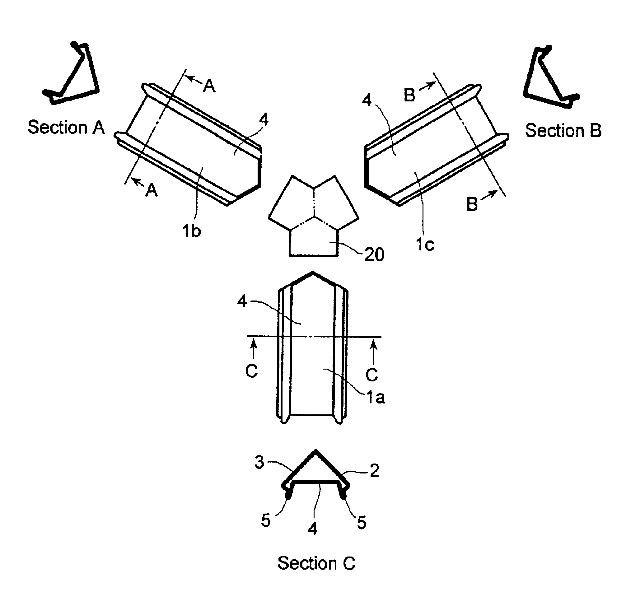
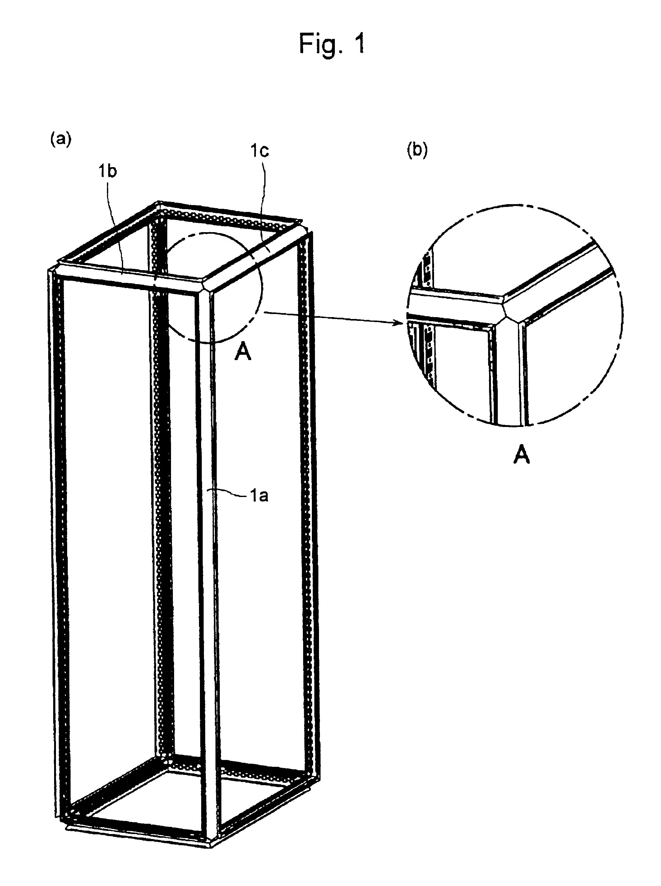
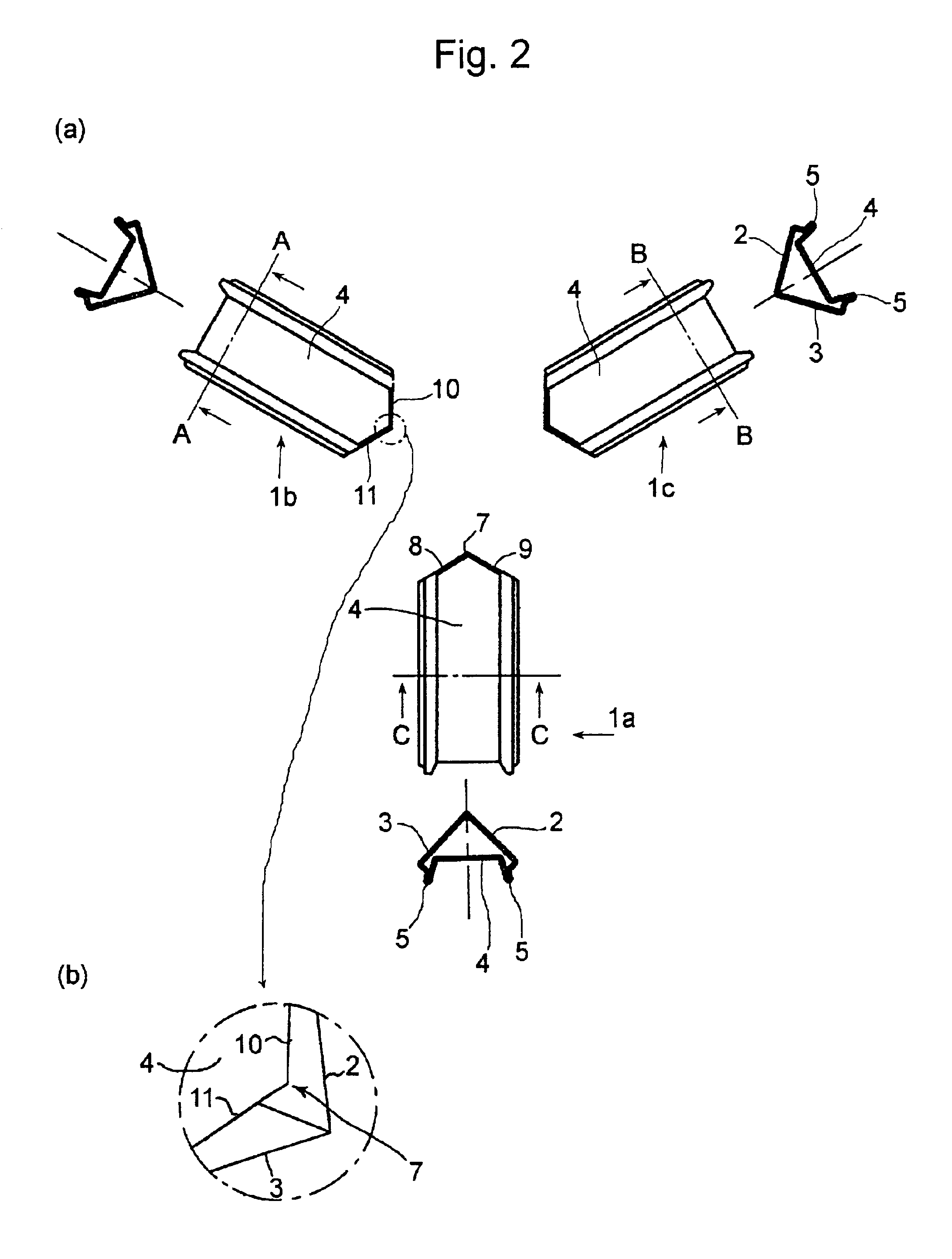
[0142]FIGS. 41 to 49 show a first embodiment of the embodiment form (D), FIG. 41 being a perspective view of a corner portion as veiwed from outside a cabinet, FIG. 42 being a front view showing the corner portion, FIG. 43 being a cross sectional view, and FIG. 44 being a perspective view of the corner portion as viewed from inside the cabinet. As shown in these drawings, the corner portion is formed by joining ends of three orthogonal frames D1 in vertical, lateral and depthwise directions.

[0143]The frames D2 according to the first embodiment are formed by folding a steel sheet into the same cross-sectional shape as shown in FIGS. 45 to 47. More specifically, the respective frames D1 comprises a recessed portion D5 as a draining portion by using side walls D32, D32 directed toward the corner to form substantially hollow projections D4, D4 on both ends of an oblique side D3 of a right-angled triangular-shaped hollow portion D2, and a right-angled folded si...


PUM


Abstract

A frame joining structure for electrical and electronic equipment housing cabinets, in which ends of frames are simplified in shape to dispense with complex cutting and which possesses excellent strength and waterproof property. Ends of outer side surfaces (4) of three mutually orthogonal frames (1a, 1b, 1c), which constitute a framework of a cabinet, are cut at two planes of ±45° relative to a plane defined by other two frames to be point-shaped. These ends are joined together directly or through a corner member (20) having the same configuration as that of the ends to constitute a firm corner portion.

Description

BACKGROUND OF THE INVENTION[0001]1. Field of the Invention[0002]The invention relates to a frame for electrical and electronic equipment housing cabinets, in which a rectangular framework of an electrical and electronic equipment housing cabinet is constituted by combining frames in vertical, widthwise and depthwise directions, and a frame joining structure.[0003]2. Prior Art[0004]With electrical and electronic equipment housing cabinets such as control panel boxes, communication panel boxes, high voltage power receiving boxes, it is common that twelve hollow frames being quadrilateral in cross sectional shape are combined to constitute a rectangular framework. Ends of the respective frames are cut at 90° relative to their lengthwise directions, and joined together by inserting a corner member having mutually orthogonal three arms into the ends of the respective frames or making use of a connection member.[0005]Cabinet outer walls such as side plates, a door and the like are mounted...

Claims


Application Information

Patent Timeline
IPC IPC(8): H02B1/30H02B1/01H02B1/00
CPCH02B1/01H02B1/308H02B1/013H02B1/014Y10T403/42Y10T403/477Y10T403/34Y10T403/345Y10T403/447Y10T403/44F16B2200/67H02B1/30
Inventor SUZUKI, KAZUMASA
Owner NITTO KOGYO KK
Why Eureka
Try Eureka