Isolation cap and bushing for circuit breaker rotor assembly

a technology of isolation cap and bushing, which is applied in the direction of circuit-breaking switch contacts, circuit-breaking switches, relays, etc., can solve the problems of dielectric failure, arcing often occurring between, and arcing between other components of circuit breaker

Inactive Publication Date: 2005-11-15
ABB SPA
View PDF22 Cites 28 Cited by
  • Summary
  • Abstract
  • Description
  • Claims
  • Application Information

AI Technical Summary

Benefits of technology

[0005]The above discussed and other drawbacks and deficiencies are overcome or alleviated by an electrically isolated rotor assembly for a circuit breaker. The electrically isolated rotor assembly includes a rotor having a first side and an opposing second side, a first isolation cap disposed on the first side, a second isolation cap disposed on the second side, and means for preventing dislocation of the first and second isolation caps from the rotor during rotation of the rotor.

Problems solved by technology

Upon the intense overcurrent conditions that result in the separation of the contacts, however, arcing often occurs between various parts in the circuit breaker.
However, arcing may occur between other components of the circuit breaker as well.
Because of the close position between each of the cassettes, and between each cassette and the operating mechanism, the spacing between poles of opposite polarity could lead to dielectric failure.

Method used


Image

  • Isolation cap and bushing for circuit breaker rotor assembly
  • Isolation cap and bushing for circuit breaker rotor assembly
  • Isolation cap and bushing for circuit breaker rotor assembly

Examples


Embodiment Construction

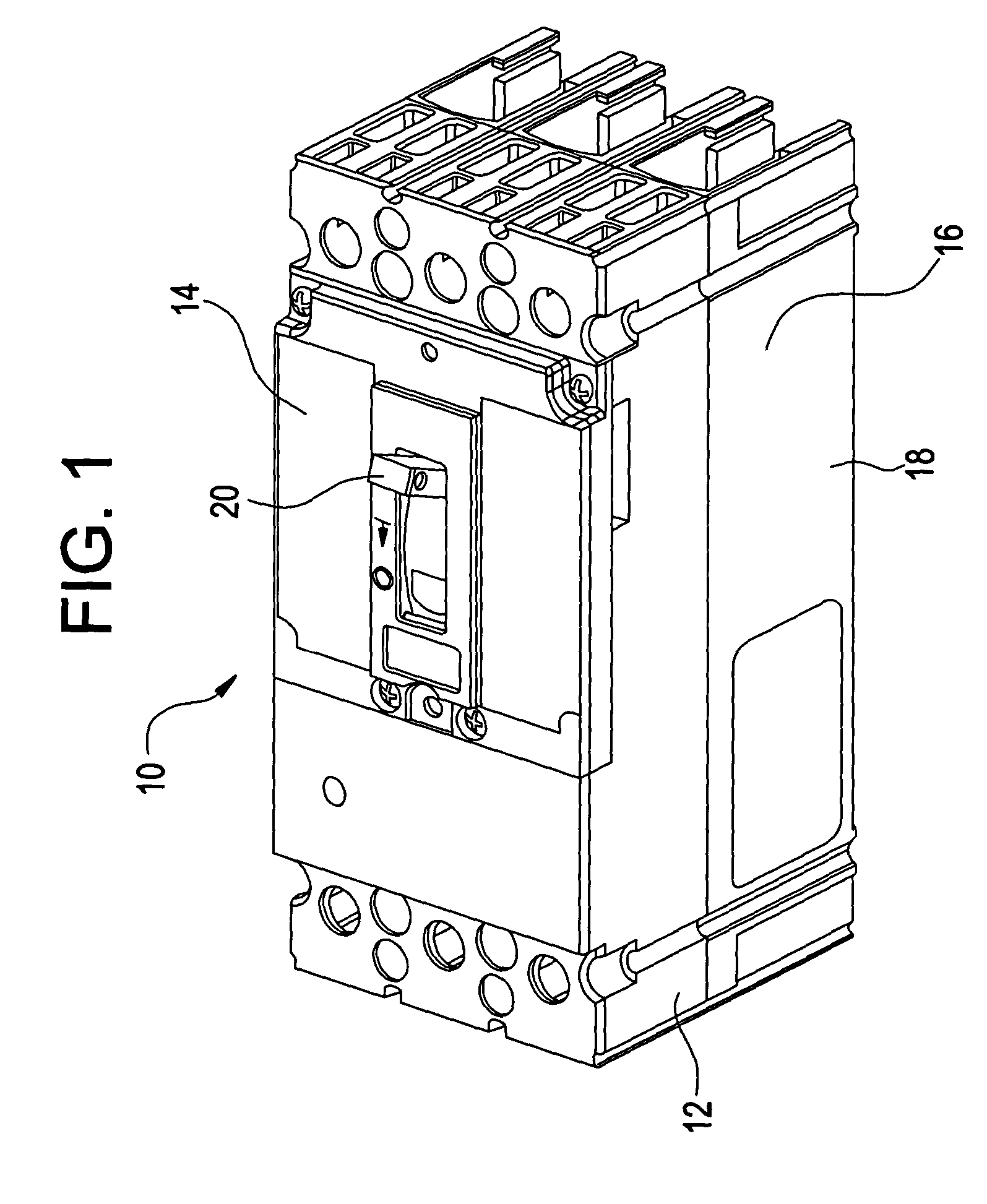
[0015]Referring to FIG. 1, an embodiment of a molded case circuit breaker 10 is generally shown. Circuit breakers of this type generally have an insulated case 16 having a cover 14 attached to a mid-cover 12 coupled to a base 18. A handle 20 extending through cover 14 gives the operator the ability to turn the circuit breaker 10“on” to energize a protected circuit (as shown in FIG. 3), turn the circuit breaker “off” to disconnect the protected circuit (not shown), or “reset” the circuit breaker after a fault (not shown). A plurality of line-side contact and load-side straps also extend through the case 16 for connecting the circuit breaker 10 to the line and load conductors of the protected circuit. The circuit breaker 10 in FIG. 1 shows a typical three phase configuration, however, the present invention is not limited to this configuration but may be applied to other configurations, such as one, two, four, or more phase circuit breakers.

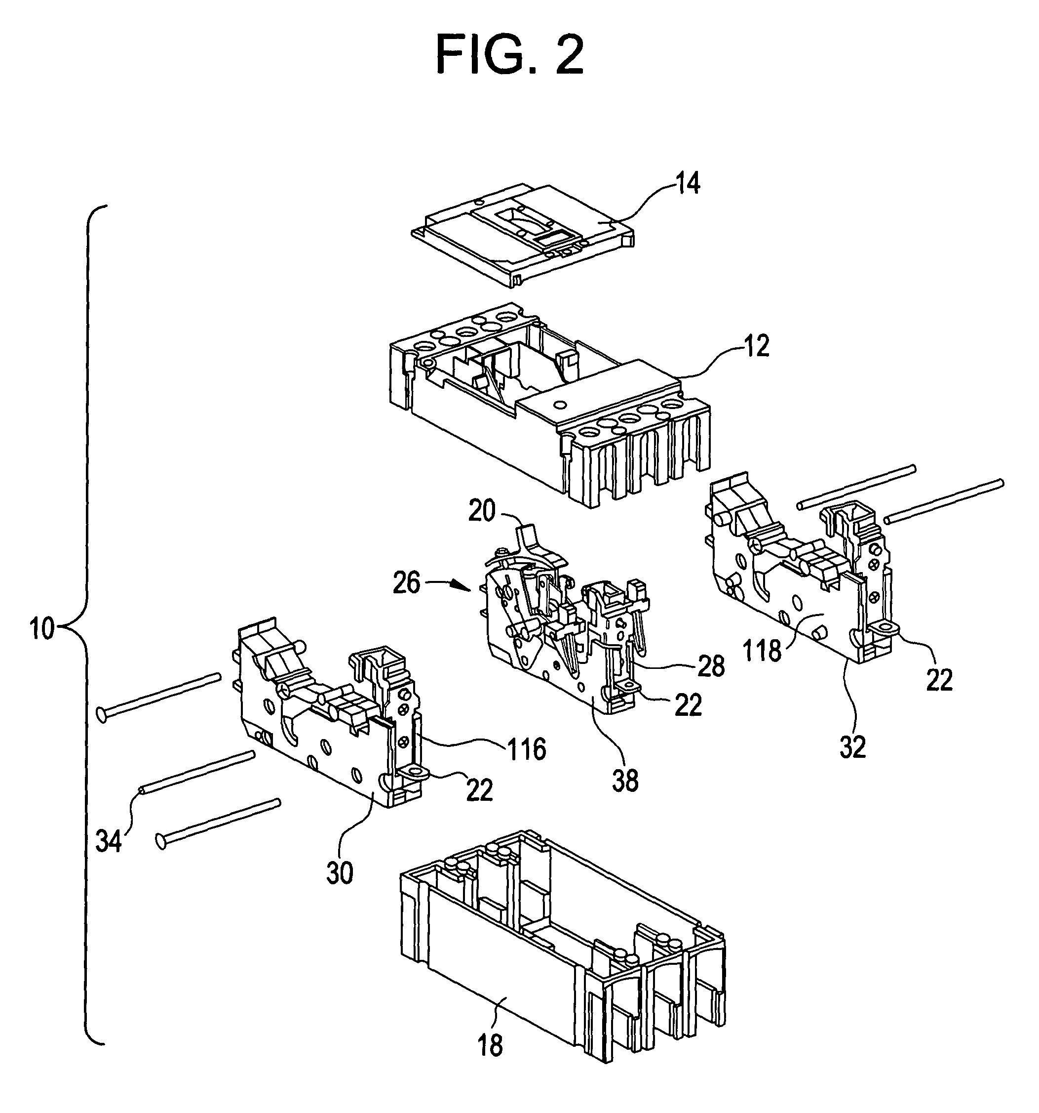
[0016]Referring to FIG. 2, the handle 20 is a...


PUM


Abstract

An electrically isolated rotor assembly for a cassette assembly of a circuit breaker includes a rotor having a first side and an opposing second side, a first isolation cap disposed on the first side, a second isolation cap disposed on the second side. Each isolation cap preferably includes a centrally located knob with a bushing surrounding each knob, wherein the bushings are sized for securement within apertures within first and second cassette half pieces.

Description

BACKGROUND OF THE INVENTION[0001]This invention relates generally to circuit breakers, and, more particularly, this invention relates to a rotor assembly with electrical isolation.[0002]A current limiting circuit breaker is generally a high current circuit interrupting device capable of substantially limiting the duration and the intensity of current destined to flow in a circuit experiencing short circuit fault. To limit the duration and the intensity of short circuit currents, a circuit breaker must, within the shortest possible time, separate its contacts. This separation of the contacts is achieved by rapidly accelerating movable contact arms through an open gap. Upon the intense overcurrent conditions that result in the separation of the contacts, however, arcing often occurs between various parts in the circuit breaker. Arcing between the contacts is usually extinguished by passing the arc through an arc dissipating means. However, arcing may occur between other components of ...

Claims


Application Information

Patent Timeline
Patent Type & Authority Patents(United States)
IPC IPC(8): H01H73/00H01H73/04
CPCH01H1/205H01H1/2058
Inventor CIARCIA, RONALDSUBRAMANIAN, ANANTHRAMNARENDER, MACHABRIGNONI, LUISKIM, SAMUELLAFFERTY, PAUL
Owner ABB SPA
Why Eureka
Try Eureka