Packet flow control apparatus and a method for controlling the same

a control apparatus and flow control technology, applied in the field of packet flow control apparatus and a method, can solve the problems of unexpected congestion of resources provided within the network, worse transfer quality from the sending side to the receiving side,

Inactive Publication Date: 2005-11-15
FUJITSU LTD
View PDF19 Cites 42 Cited by
  • Summary
  • Abstract
  • Description
  • Claims
  • Application Information

AI Technical Summary

Benefits of technology

[0007]The object of the present invention is to provide an improved packet flow control apparatus and a method of the same, used in a network, such as an internet, in which the packet flow control can be realized for each control unit by using a small amount of hardware.

Problems solved by technology

In this case, however, if a packet, which does not comply with the above information, is sent from the user side or sending side, the resources provided within the network are unexpectedly congested (i.e., the resources becomes busy) so that the transferring quality from the sending side to the receiving side may be worse because of congestion of the network.

Method used


Image

  • Packet flow control apparatus and a method for controlling the same
  • Packet flow control apparatus and a method for controlling the same
  • Packet flow control apparatus and a method for controlling the same

Examples


first embodiment

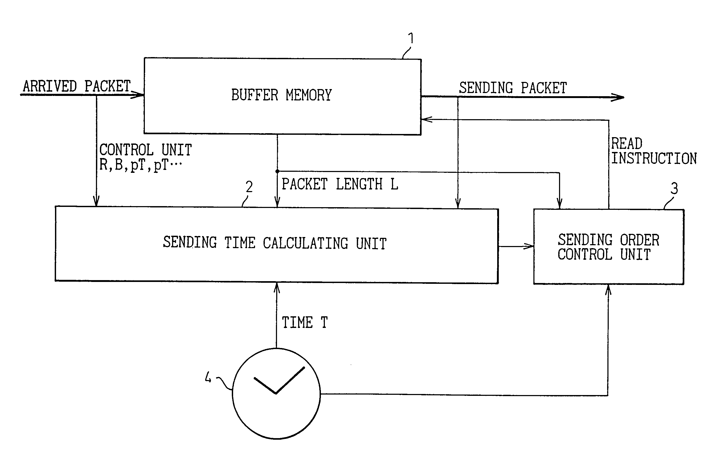
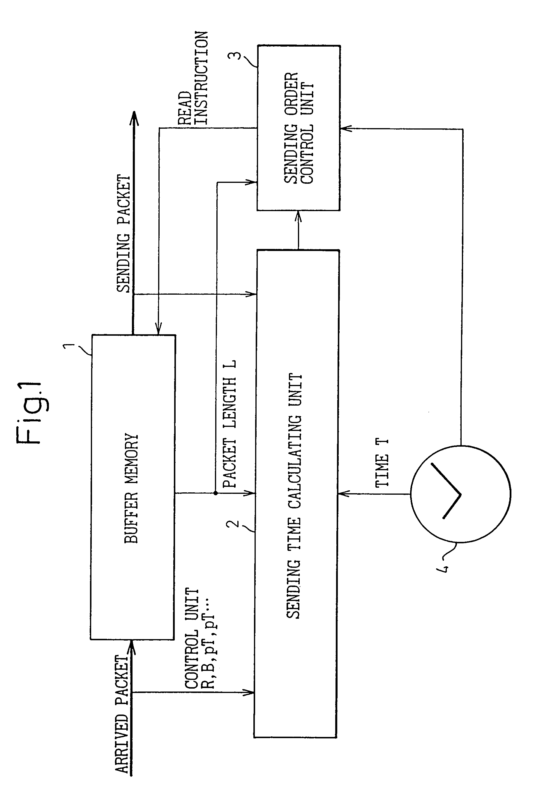
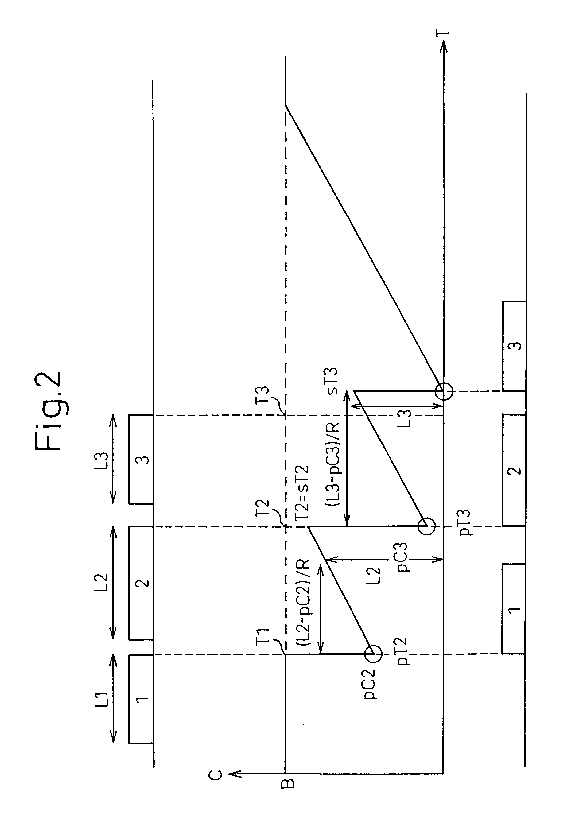
[0086]A calculation method of the sending time sT in the sending time calculating unit 2 in the embodiment (2) will be explained in detail below. In this case, although the steps of the write operation to the buffer memory 1 of the arrived packet are the same as the steps shown in FIG. 5 in the embodiment (1), the detailed calculation of the sending time sT is different from the first embodiment, as shown in FIG. 11. Further, the steps of the read operation from the buffer memory 1 are the same as the steps shown in FIG. 6 in the embodiment (1).

[0087]As mentioned above, the memory 21 stores, for each control unit of the arrived packet, the sending rate R, the token packet size B and the recovery time bT of the upper limit value of the pre-packet, as parameters.

[0088]In FIG. 11, when writing the arrived packet into the buffer memory 1, the control unit of the packet is identified based on the header information of that packet, and the parameter for the identified control unit is read...

third embodiment

[0110]In the embodiment (4), the sending time sT is calculated at the time when the arrived packets are read out from the buffer memory. As well as the third embodiment, the sending time T is calculated at the time when the packet is read out from the memory 21, and not stored for each packet in the sending order control unit 3 in the embodiment (4). In the calculation method of the sending time, the number of parameters to be stored in the memory 21 can be reduced by performing the same method as the embodiment (2) shown in FIG. 8.

[0111]In the embodiment (4), the steps of the write operation of the packet to the buffer memory 1 are the same as the steps of the embodiment (3) shown in FIG. 12, and the steps of the read operation of the packet from the buffer memory 1 are the same as the steps of the embodiment (3) shown in FIG. 13. On the other hand, the detailed steps of the read time calculation in the flowchart shown in FIG. 13 are different from the step of the embodiment (3), a...

an embodiment (

[0137](An embodiment (b) for managing the sending order)

[0138]Next, the management of the sending order in the sending order control unit 2 is explained in detail below.

[0139]In the above embodiment (a) for managing the sending order, the sending time of the new packet is calculated in the sending time calculating unit 2, and is sent to the sending order control unit 3. Further, the pointer link information is read out from the sending order control unit 3, and when the read instruction of the packet is sent to the buffer memory 1, the pointer link information in the pointer link memory 33 of the sending order control unit 3 are added or deleted so that the state of the pointer link is changed. In this case, it is necessary to update collectively the contents of the pointer link information that are provided after the pointer link information newly added or deleted. In these processes, however, when there is much pointer link information after adding or deleting pointer link informa...


PUM


Abstract

A packet flow control apparatus performing flow control of packets each having variable length, includes: a buffer memory for temporarily accumulating arrived packets until a sending time of each packet; a counter updated based on a rate determined in accordance with a packet length calculated by a counter value of the counter and limited flow of packets; a sending time determining section for determining the sending time of each packet based on the counter value and a present time; and a sending order control section for managing a sending order of each packet accumulated in the buffer memory, and for sending a read instruction of each packet to the buffer memory, based on the sending time determined by the sending time determining section.

Description

BACKGROUND OF THE INVENTION[0001]1. Field of the Invention[0002]The present invention relates to a packet flow control apparatus and a method for controlling the flow of packets on a network such as the Internet.[0003]2. Description of the Related Art[0004]Recently, in communication systems using variable length packets such as the Internet, provision of a so-called “quality-guarantee type service”, which assures the quality so as to avoid a delay at an end-to-end connection or a communication band to be always occupied, has been examined by IETF (Internet Engineering Task Force) and the like.[0005]In the above-mentioned quality-guarantee type service, the information including a flow of sending packets, etc., is previously provided in accordance with a control unit formed of each packet flow, collection of packet flow, a destination of packet, etc., in the network of a user side or a sending side. Further, various resources provided within the network are previously reserved for th...

Claims


Application Information

Patent Timeline
Patent Type & Authority Patents(United States)
IPC IPC(8): H04L12/56H04L47/22
CPCH04L47/10
Inventor KAWASAKI, TAKESHISOUMIYA, TOSHIONAKAMICHI, KOJI
Owner FUJITSU LTD
Why Eureka
Try Eureka