Torque angle sensing system and method with angle indication

Inactive Publication Date: 2005-11-15
SPX CORP
View PDF13 Cites 47 Cited by
  • Summary
  • Abstract
  • Description
  • Claims
  • Application Information

AI Technical Summary

Benefits of technology

[0022]There has thus been outlined, rather broadly, the more important features of the invention in order that the detailed description thereof that follows may be better understood, and in order that the prese

Problems solved by technology

Fastener preload control through monitoring of fastener torque alone, however, yields unpredictable and inconsistent results due in part to varying friction between the mating threads and beneath the fastener head.
Where it has been attempted to obtain greater uniformity through use of lubricants or the like, results have continued to be unsatisfactory.
Such arrangements still do not directly measure fastener tension, and in addition require expensive assembly and control hardware.
Arrangements of t

Method used


Image

  • Torque angle sensing system and method with angle indication
  • Torque angle sensing system and method with angle indication
  • Torque angle sensing system and method with angle indication

Examples


Embodiment Construction

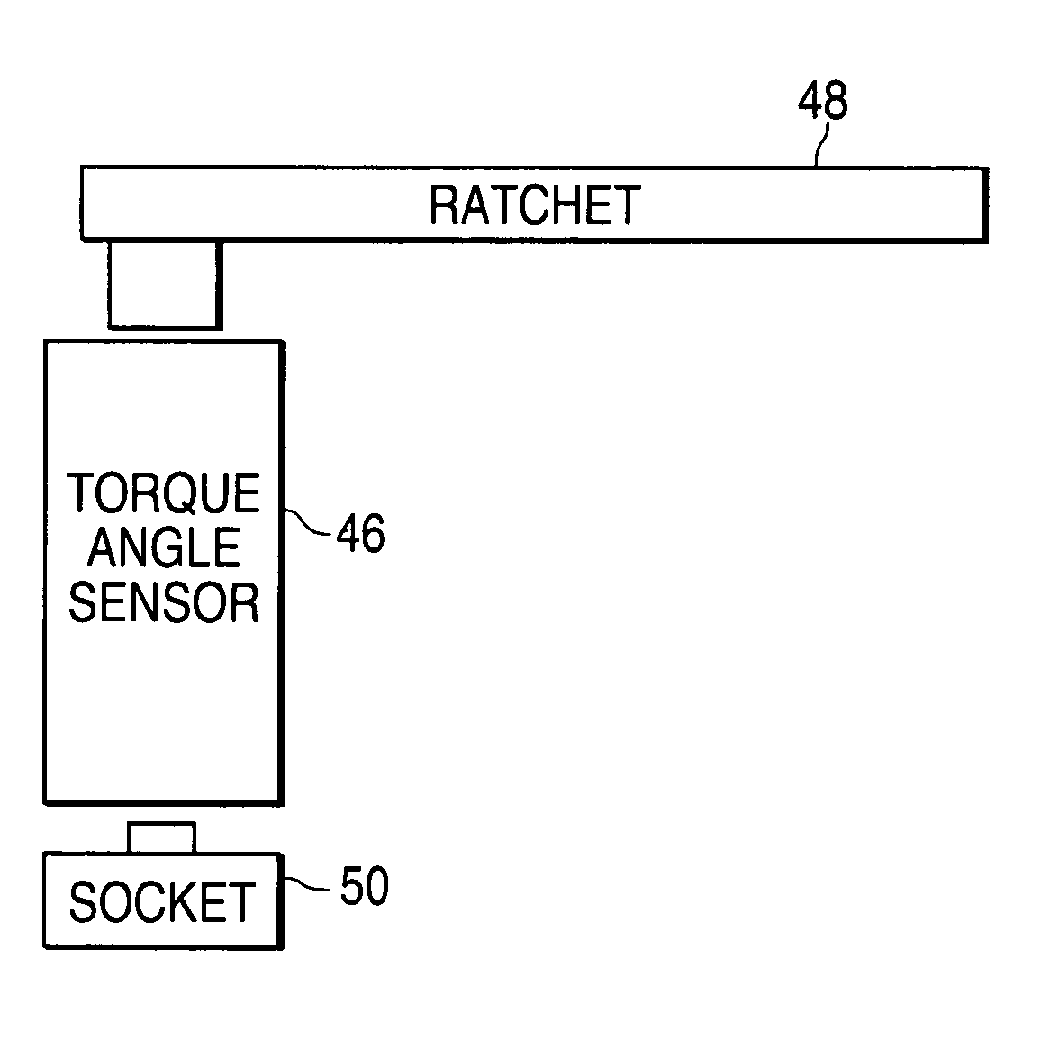
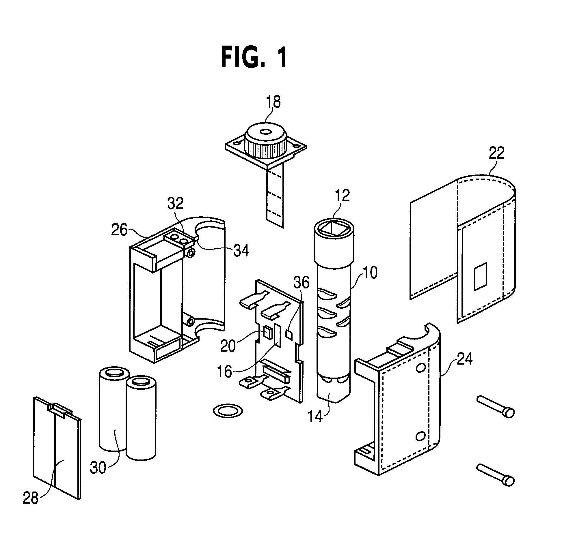
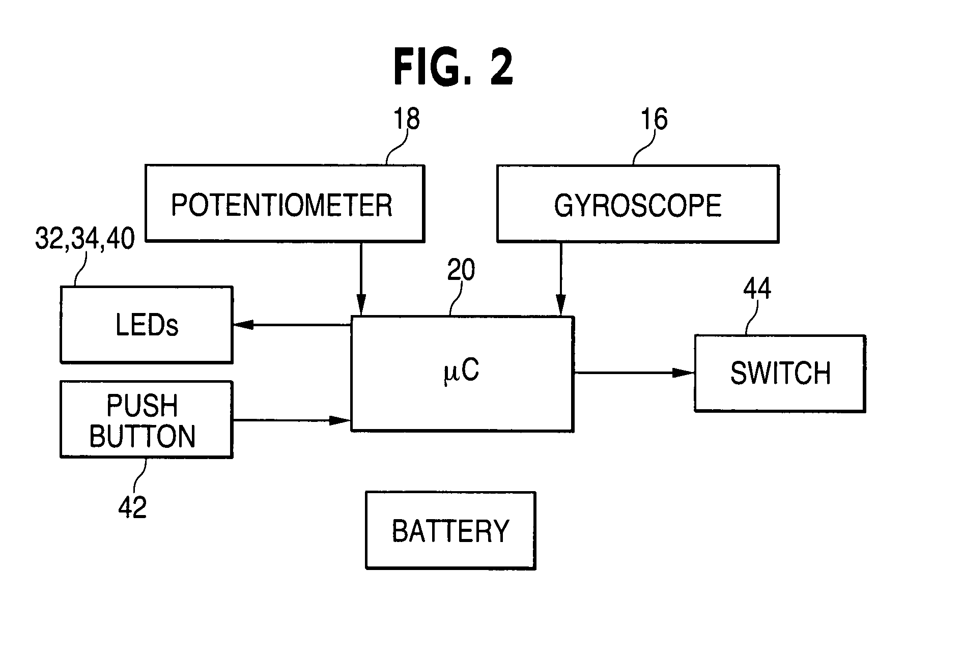
[0031]A preferred embodiment of the present invention provides a device that measures an angle of rotation of a fastener after a specified torque has been applied to the fastener. As illustrated in FIG. 1, a preferred embodiment includes a shaft 10 is inserted between a socket and torque wrench. The wrench end 12 is connected to the torque wrench. The socket end 14 is connected to a socket that is chosen for the appropriate fastener. The shaft 10 is linked to an angular rate sensor 16 such as a gyroscope. Additionally, the apparatus contains an angle selector 18. The angle selector 18 can be a potentiometer, which allows for angle selection in about five degree increments, or a resistance ladder, which allows for finer angle selection. The angle selector 18 varies the voltage and resistance. Any other suitable resistance adjuster can be used in place of either the ladder or the potentiometer.

[0032]The shaft 18 does not need to be a separate component between a socket and wrench. The...


PUM


Abstract

A device used for measuring the angle of torque beyond a specific reference point. The device is comprised of a tool that applies torque to a fastener, an adapter that is attached to the fastener to transfer the torque from the tool, and an apparatus that connects a first end to the tool and a second end to the adapter. The apparatus comprises an angle selector that is adjustable to the desired torque angle, an angle rate sensor that measures the speed and direction of the torque applied, a processor which calculates the current angle from the rate sensor measurements, a zero point indicator that serves as the basis point for the processor to calculate the selected angle, and an angle indicator that indicates the current angle of rotation.

Description

FIELD OF THE INVENTION[0001]The present invention relates generally to a torque angle measuring device. More particularly, the present invention relates to a torque angle sensor that measures the current angle of rotation applied beyond a point of reference.BACKGROUND OF THE INVENTION[0002]The importance of accurately and consistently controlling tension or preload applied to threaded fasteners increases with precision or criticality of parameters and tolerances of the assembly as a whole. This is particularly true in mass production of precision-designed equipment which may later be subjected to maintenance or repair, following which load applied to the assembly fasteners must be substantially the same as that applied during original manufacture. For example, in the manufacture of internal combustion engines designed for high performance and fuel economy, the head is fastened to the engine block with a plurality of bolts prior to final machining of various block / cylinder critical s...

Claims


Application Information

Patent Timeline
IPC IPC(8): B25B23/142B25B23/14G01L5/24
CPCB25B23/14B25B23/1425G01L5/24
Inventor MCGEE, PHILLIPKOCHIE, ROBERTRIBEIRO, DURVAL
Owner SPX CORP
Why Eureka
Try Eureka