
Engine cogeneration system

a cogeneration system and engine technology, applied in the direction of machines/engines, reciprocating combination engines, electric generator control, etc., can solve the problems of tern control, difficult to follow in both load variation of heat demand and power demand in an appropriate manner, and no consideration is made to make a heat demand network

Active Publication Date: 2005-11-22
HITACHI LTD
View PDF5 Cites 32 Cited by
  • Summary
  • Abstract
  • Description
  • Claims
  • Application Information

AI Technical Summary

Problems solved by technology

In the conventional techniques, no consideration is made to make a network for heat demand, and have a problem in terms of controlling both of heat demands and power demands in each household to follow their variation in each household.
Specifically, in conventional techniques, since network for heat demand is not constructed, the driving of the power generator in each household is to be controlled irreverent to the heat demand in the household, resulting in the problem in terns of control due to making it difficult to follow in both load variations of the heat demand and power demand in an appropriate manner.
Consequently, in the cogeneration systems in the conventional techniques, it is difficult to follow the variation both in the power load and the heat load, and at this time, in the conventional techniques, the power source is driven to meet the heat load.
This results in surplus power or power shortage, this in turn increase the period for conducting reverse current or power interchange within the cooperative systems, and reduces the economical merit obtainable by the cogeneration.

Method used


Image

  • Engine cogeneration system
  • Engine cogeneration system
  • Engine cogeneration system

Examples


Embodiment Construction

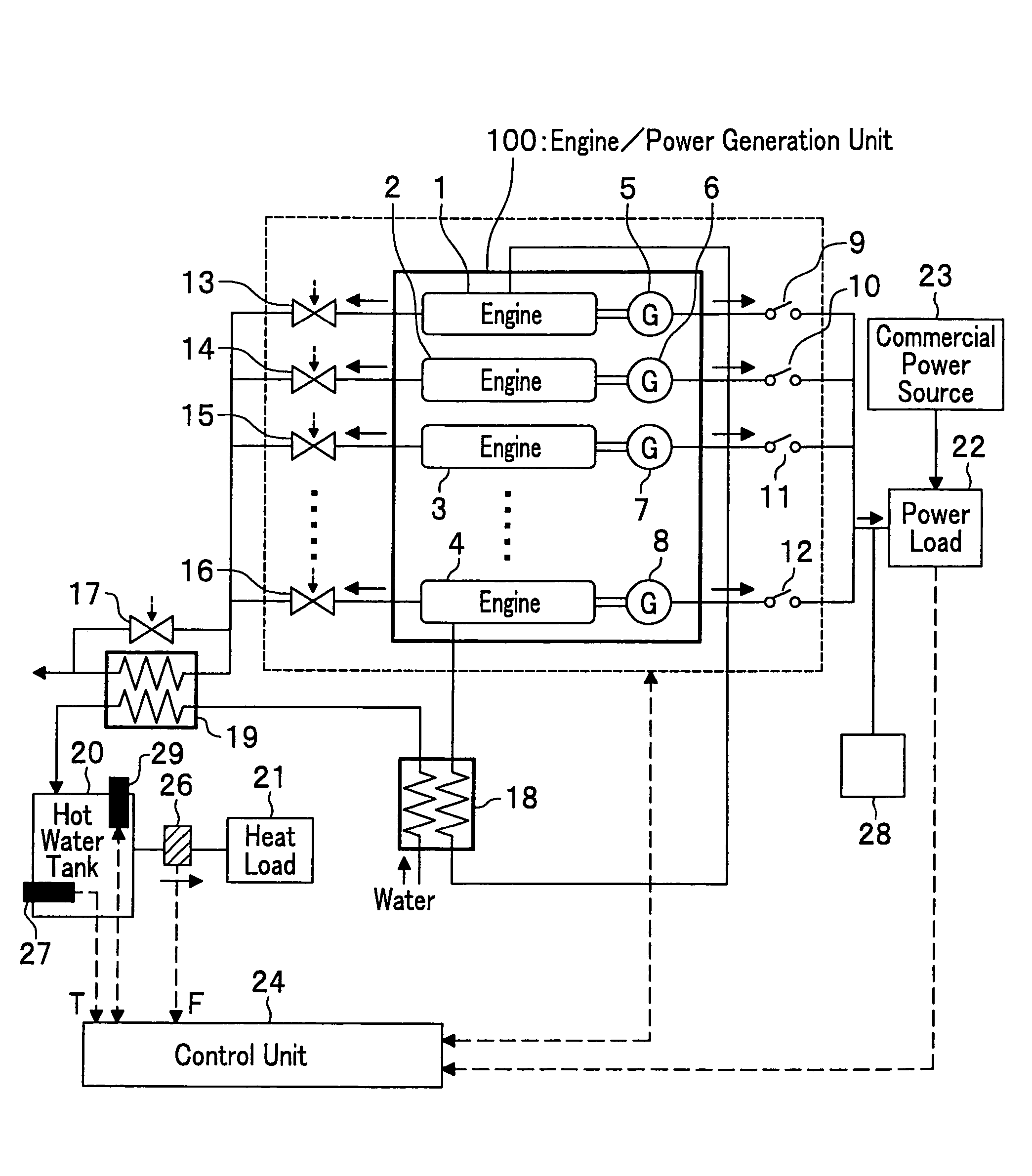
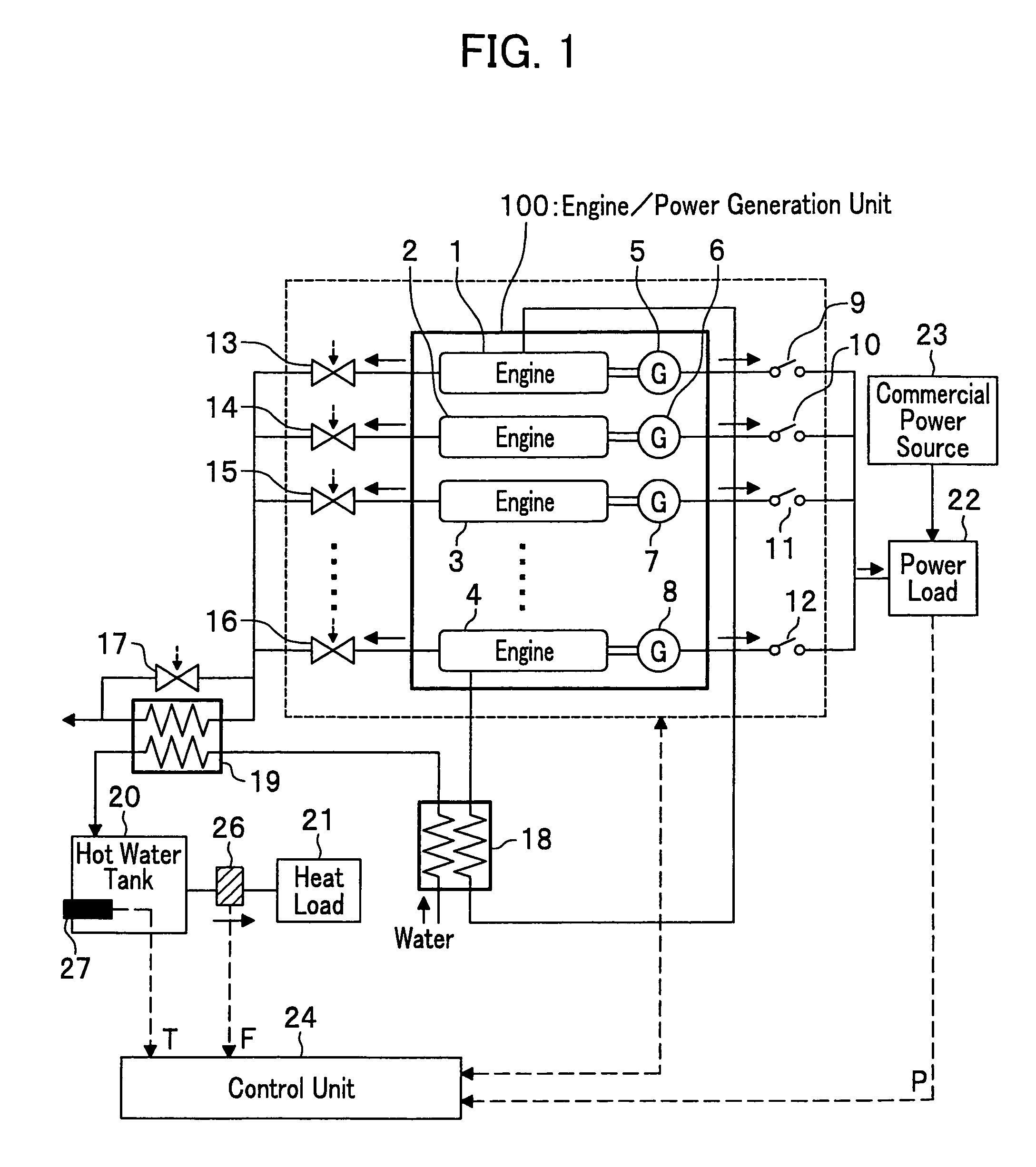
[0031]Referring to drawings, embodiments of an engine cogeneration system according to the present invention will now be described.

[0032]FIG. 1 shows one embodiment, where numeral 100 is an engine / power generator unit. The engine / power generator unit 100 is composed of a plurality of engines / power generators (four in this figure) as shown in FIG. 1, and comprises a combination of engines 1 to 4, with generators 5 to 8. For this reason, engine / power generators are expressed as engine / power generator (1-5), engine / power generator (2-6), engine / power generator (3-7), and engine / power generator (4-8).

[0033]The electric power generated by each of the power generators 5 to 8 is configured to be supplied to power load 22 comprising household electric equipment such as lights. The power P being supplied from each of the power generators 5 to 8 to the power load 22 is detected by a power meter (not shown) and is inputted to a control unit 24.

[0034]In this embodiment, it is configured that po...


PUM


Abstract

In an engine cogeneration system in which power generators 5 to 8 are driven by a plurality of engines 1 to 4 to thereby supply electric power to power load 22 of a general household, at the same time, heat produced by cooling each of the engines 1 to 4 and heat generated from the exhaust gas are recovered by heat exchangers 18 and 19 to be stored as hot water into a hot-water tank 20 to supply heat to heat load 21 of the general household, the amount of power to be supplied and of the amount of heat to be supplied are controlled by a number of the engines 1 to 4 and the combustion modes of these engines 1 to 4. This engine cogeneration system can follow both the head demand and power demand in a high efficiency.

Description

BACKGROUND OF THE INVENTION[0001]1. Field of the Invention[0002]The present invention relates to a cogeneration apparatus utilizing an internal combustion engine, and particularly to an engine cogeneration system suitably for placing on a residence to supply both electric power and heat for use in a household.[0003]2. Description of the Related Arts[0004]Conventionally, a so-called cogeneration system has been known in which a power generator is driven by an engine (internal combustion engine) utilizing gasoline or municipal gas as fuel to obtain electric power from the power generator and at the same time, exhaust heat from the engine is recovered to be utilized as a heat source. In recent years, a system in which the cogeneration apparatus is placed on a residence to obtain both electric power and heat consumed in the household therefrom, i.e., the engine cogeneration system has been made attracted from the viewpoint of saving energy.[0005]The conventional techniques have been kno...

Claims


Application Information

Patent Timeline
Patent Type & Authority Patents(United States)
IPC IPC(8): F02D29/06F02B1/12F02D43/00F02B1/00F02B11/00F02G5/00F02G5/04F02B73/00F02P5/15F24H1/00F25B49/00H02J3/46F24D18/00
CPCF02G5/04F24H2240/06Y02E20/14Y02T10/166Y02T10/12F24D18/00F24D2101/70F24D2103/13
Inventor SHIMADA, ATSUSHIIDE, KAZUMASAYAMAOKA, SHIRO
Owner HITACHI LTD
Learn More