Latch timing mechanism for a two-step roller finger cam follower

a technology of roller finger cam follower and latch timing mechanism, which is applied in the direction of valve arrangement, mechanical equipment, machines/engines, etc., can solve the problems and achieve the effect of less rigorous timing of hydraulic pressurizing and depressurizing of latch pins

Inactive Publication Date: 2005-11-22
DELPHI TECH INC
View PDF4 Cites 66 Cited by
  • Summary
  • Abstract
  • Description
  • Claims
  • Application Information

AI Technical Summary

Problems solved by technology

The timing of the hydraulic pressurizing and de-pressurizing of the latch pin thus is much less rigorous than in the prior art.

Method used


Image

  • Latch timing mechanism for a two-step roller finger cam follower
  • Latch timing mechanism for a two-step roller finger cam follower
  • Latch timing mechanism for a two-step roller finger cam follower

Examples


Embodiment Construction

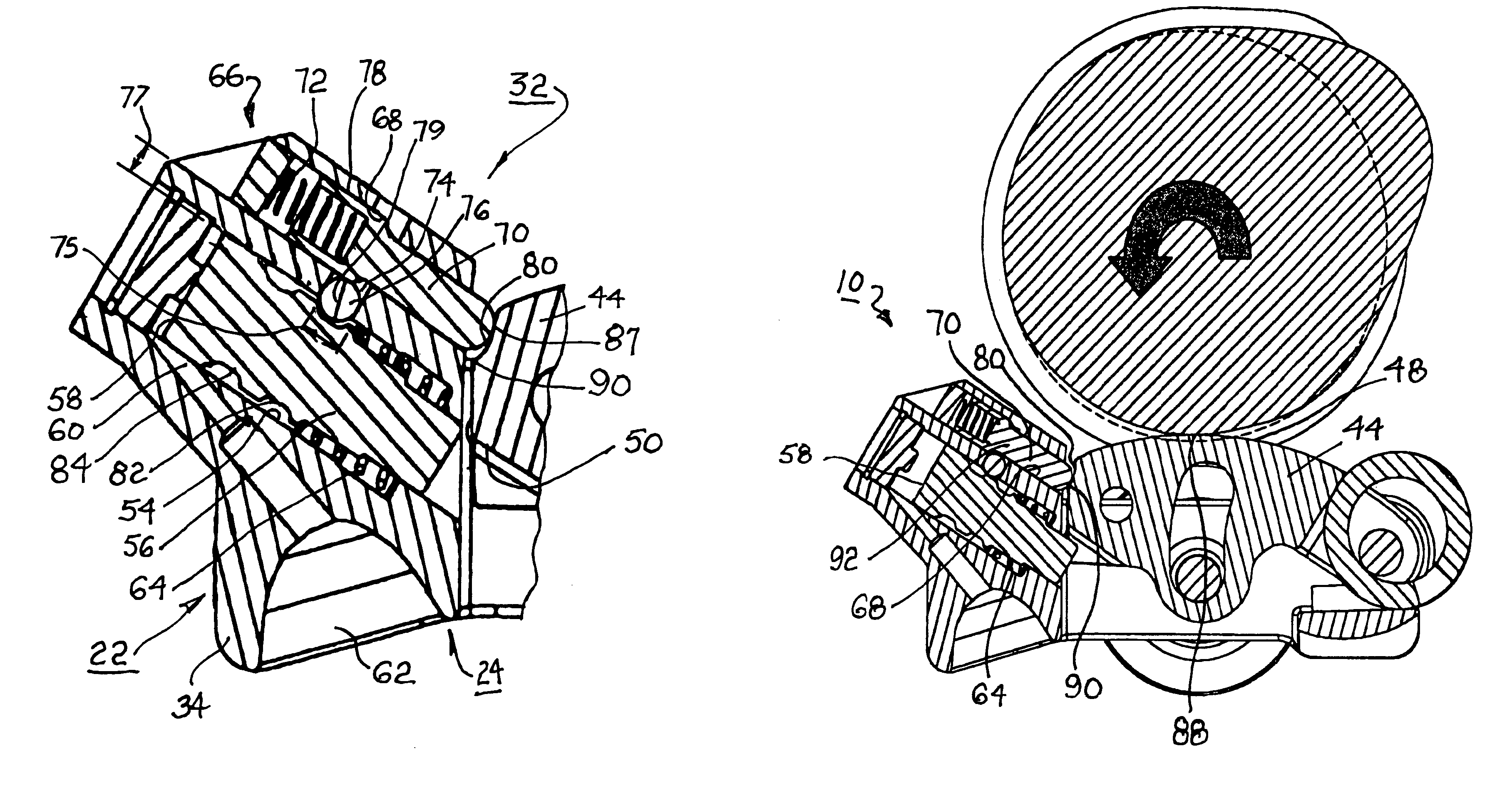
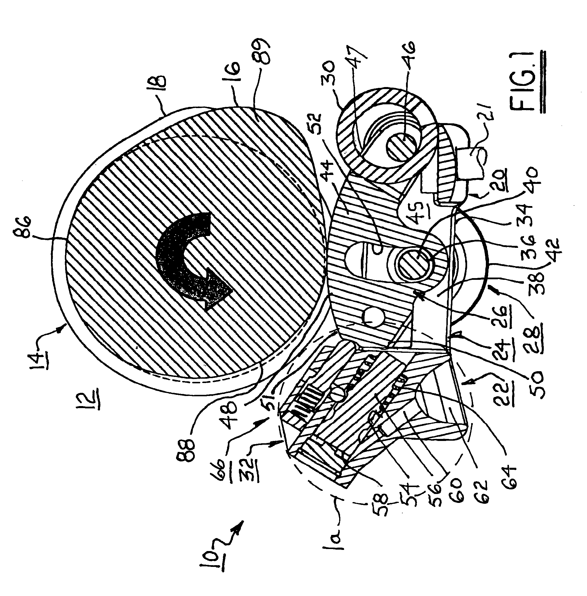
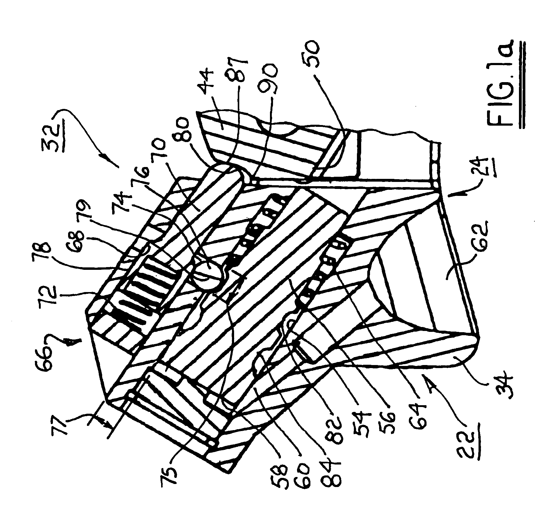
[0017]Referring to FIGS. 1 through 3, improved two-step roller finger follower 10 is shown. RFF 10 is intended for use with an internal combustion engine 12 comprising a cam 14 having a central high-lift lobe 16 flanked by a pair of low-lift lobes 18. High-lift lobe 16 includes base circle portion 86 and positive lift region 89. The high lift lobe is either enabled by latching of a central slider arm 44 pivotable within the RFF, or disabled by unlatching the central slider arm and allowing it to pivotably follow the high-lift lobe in lost motion as further described below.

[0018]Referring to FIG. 1, a pallet end 20 of RFF 10 is provided for engaging a valve stem 21 and a socket end 22 of RFF 10 is provided for engaging the hemispherical head of a hydraulic lash adjuster (not shown) in known fashion, the valve stem and socket head being conventional elements of engine 12. RFF 10 includes body assembly 24, slider arm assembly 26, spool roller assembly 28, lost motion spring 30, and lat...


PUM


Abstract

In a two-step roller finger cam follower, a slider arm for engaging a high-lift cam lobe is pivotally mounted to the body and can variably engage a latch pin slidably disposed in a latch pin channel. A second channel in the body opens onto the slider arm and contains a timing pin that rides on an eccentric surface of the slider arm to extend or retract the timing pin. A bore between the latch pin channel and the timing pin channel contains a ball controlled by the timing pin to lock the latch pin into an engaged or disengaged position. The cam lobe has an undercut region such that the latch pin is allowed to move between engaged and disengaged position only when the slider arm is in the undercut region of the cam lobe. The latch pin can move only when the timing pin permits.

Description

TECHNICAL FIELD[0001]The present invention relates to roller finger followers used for variable valve actuation in overhead cam type internal combustion engines, and more particularly to a variable actuation roller finger follower wherein a timing pin mechanism is disposed adjacent a latch pin such that the latch pin can engage with and disengage from a high-lift slider only when the slider is on a “negative lift” portion of the associated high-lift cam lobe.BACKGROUND OF THE INVENTION[0002]Roller finger followers (RFF) are widely used in overhead cam internal combustion engines to sequentially open and close the cylinder intake and exhaust valves. In a typical application, the RFF serves to transfer and translate rotary motion of a cam shaft lobe into a pivotal motion of the RFF to thereby open and close an associated valve.[0003]It is known that, for a portion of the duty cycle of a typical multiple-cylinder engine, the performance load can be met by a functionally smaller engine ...

Claims


Application Information

Patent Timeline
Patent Type & Authority Patents(United States)
IPC IPC(8): F01L1/18F01L13/00
CPCF01L1/185F01L13/0036F01L1/14F01L2105/00F01L2001/186F01L2305/00
Inventor FISCHER, THOMAS H.LIPINSKI, ANDREW J.KUNZ, TIMOTHY W.HENDRIKSMA, NICK J.
Owner DELPHI TECH INC
Why Eureka
Try Eureka