Navigation system for an aircraft and associated command process

a navigation system and aircraft technology, applied in the field of aircraft navigation system, can solve the problems of difficult, even for experienced pilots, to determine the right moment for extending the various configurations of the high, and the classic approach process can reveal itself as annoying, and achieve the effect of convenient determination and facilitation of pilots' understanding of the actions

Active Publication Date: 2011-09-27
AIRBUS OPERATIONS (SAS)
View PDF26 Cites 43 Cited by
  • Summary
  • Abstract
  • Description
  • Claims
  • Application Information

AI Technical Summary

Benefits of technology

[0012]An indication for the extension of the portion of the high-lift devices involved is as such available to the pilot, which reduces the attention needed for this function, even when the approach path is relatively complex.
[0018]This type of solution enables good anticipation of the right moment for extending the high-lift devices by the pilot.
[0021]The indication displayed can be a function of the portion of the high-lift devices involved, which facilitates the pilot's understanding of the actions to be carried out.
[0022]The estimated speed for extending the involved portion of the high-lift devices is for instance a function of a limit speed for stability prior to this extension, for instance, by multiplying this limit speed by a coefficient comprised between 1.01 and 1.1 or by adding a margin comprised between 1 kt and 10 kt. The estimated speed for extending the involved portion of the high-lift devices can as such be easily determined.

Problems solved by technology

On the other hand, the classic approach process can reveal itself as annoying from the perspective of sound nuisances on the ground as a result of the progress at relatively low intermediate altitude of the aircraft over a considerable portion of its path.
As such, it is understood that speed and altitude vary simultaneously and can in addition, be linked one to the other in a way specific for each approach (for which the principal features are determined by the flight management system), it becomes difficult, even for an experienced pilot, to determine the right moment for extending the various configurations of the high-lift devices, by only observing the actual flight parameters.

Method used


Image

  • Navigation system for an aircraft and associated command process
  • Navigation system for an aircraft and associated command process
  • Navigation system for an aircraft and associated command process

Examples


Embodiment Construction

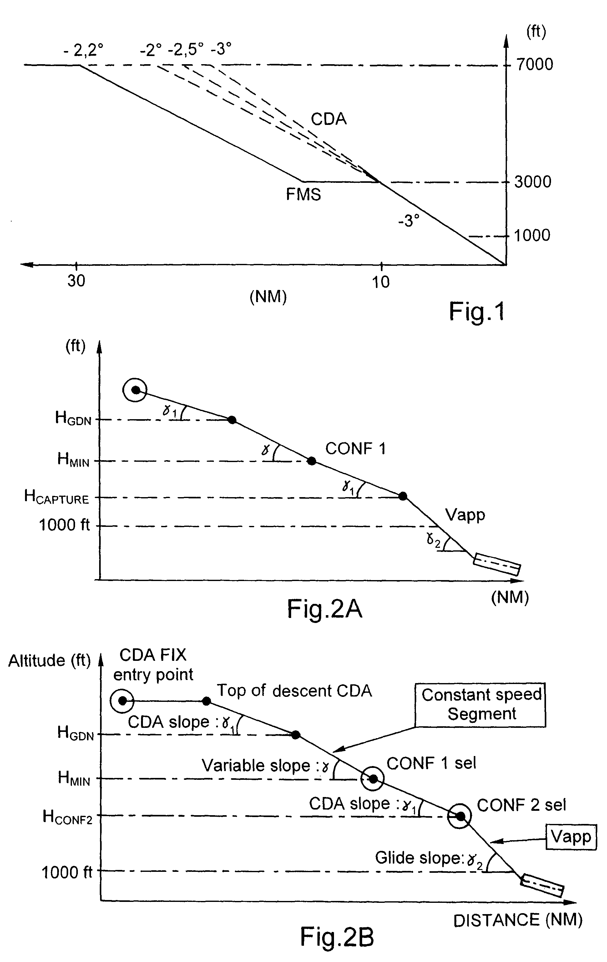
[0043]On the first figure, the landing procedure used as reference is illustrated. This procedure is the one generally used in a flight management system (FMS) of an aircraft.

[0044]In the example selected, it is assumed that the aircraft initially is beginning its descent at a given speed and an altitude of 7000 feet (or 2133.6 meters). (In the description of the paths that follows, the altitude values given are to be considered with respect to the terrain—such an altitude with respect to the terrain is sometimes called “height”.) When this aircraft wants to land at an airport, it starts a first phase of descent during which, at constant speed, it moves from an altitude of 7000 feet to 3000 feet. Once this intermediate altitude of 3000 feet is reached, the aircraft slows down, then, progressively, extends its slats and wing flaps to the first intermediate position (here generally, the wing flaps remain in the retracted position) while continuing its deceleration phase. On the figure...


PUM


Abstract

A navigation system for an aircraft, including a calculator of an estimated flight path for the aircraft; a device for determining an estimated value of a flight parameter that corresponds to an estimated speed for the extension of at least a portion of the high-lift devices of the aircraft; and a display of an indication for such estimated value. A command process for such a system and an aircraft equipped with such a system are also disclosed.

Description

CROSS-REFERENCE TO RELATED APPLICATIONS[0001]This application claims priority to French Application No. 0508212, filed Aug. 1, 2005, U.S. Provisional Application No. 60 / 644,533, filed Jan. 19, 2005, U.S. Provisional Application No. 60 / 645,050, filed Jan. 21, 2005 and U.S. Provisional Application No. 60 / 714,341 filed Sep. 7, 2005, the entire contents of which are hereby incorporated by reference.BACKGROUND OF THE INVENTION[0002]1. Field of the Invention[0003]The invention involves an aircraft navigational system and a related command process.[0004]2. Discussion of the Background[0005]The approach phase prior to landing of an aircraft usually includes two principal stages: a descent at a considerably constant speed from a cruising altitude to an intermediate altitude (generally 3000 feet, or about 1000 m) and a deceleration while maintaining this intermediate altitude to a considerable extent. After these two principal stages, the glide slope for the airport is intercepted, and exactl...

Claims


Application Information

Patent Timeline
Patent Type & Authority Patents(United States)
IPC IPC(8): G05D1/04G01C23/00
CPCG01C23/00
Inventor FERRO, DANIELVAN BOVEN, MACHIEL
Owner AIRBUS OPERATIONS (SAS)
Why Eureka
Try Eureka