Ignition apparatus for engine

Inactive Publication Date: 2005-11-22
DENSO CORP
View PDF18 Cites 2 Cited by
  • Summary
  • Abstract
  • Description
  • Claims
  • Application Information

AI Technical Summary

Benefits of technology

[0004]In view of foregoing problems, it is an object of the present invention to avoid electric conduction failure between a plug section and a coil section.
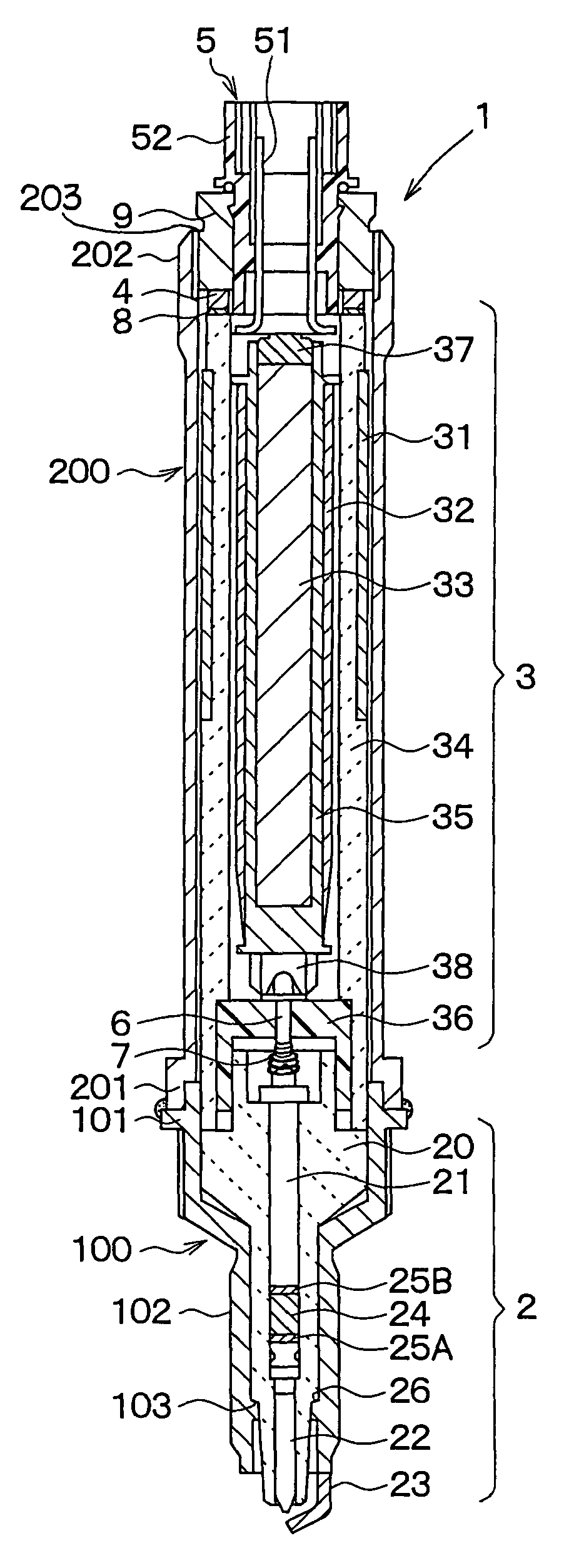
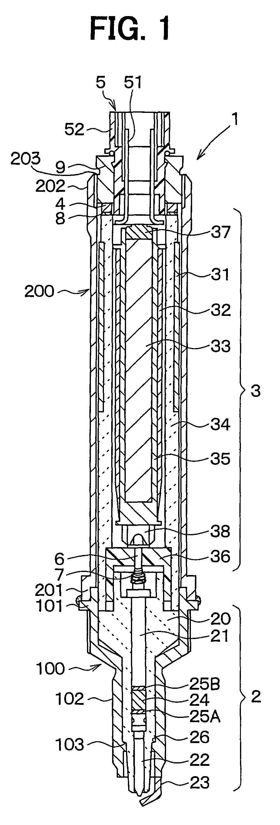
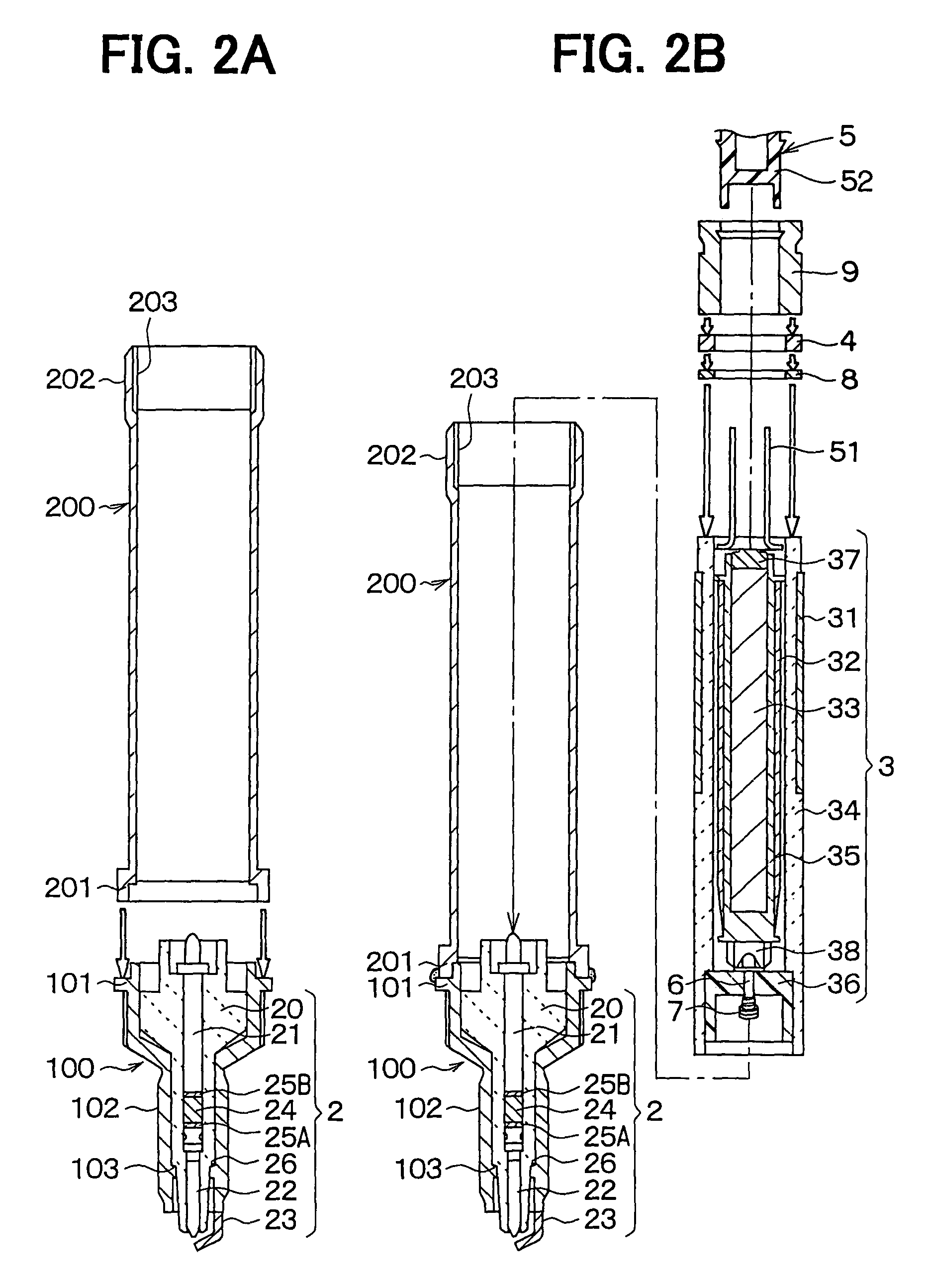
[0005]In the present invention, a plug section and a coil section are integrated into an ignition apparatus and are mounted on the cylinder head of an engine. The plug section sparks at tip end between a center electrode and a ground electrode. The coil section has a primary coil and a secondary coil, and supplies high voltages to the plug section. When the plug section is joined with the coil section, the center electrode is electrically connected with the secondary coil via connection terminal members. The connection is maintained by spring force, and is not apt to be disconnected. Thus, electric conduction failure can be avoided. The terminal members can be a coil spring, a blade spring, bent wires and so on.

Problems solved by technology

However, in case that the stem is connected with the high voltage terminal by screwing or crimping, the connection between the stem and the high voltage terminal is apt to be disconnected due to vibration, causing failure in electric conduction.

Method used


Image

  • Ignition apparatus for engine
  • Ignition apparatus for engine
  • Ignition apparatus for engine

Examples


fifth embodiment

[0058]In the fifth embodiment, as shown in FIG. 9, the coil spring 7 is mounted on the stem 21. On the lower end of the intermediate electrode 6, a dish-shaped end terminal 61 is joined by welding or crimping. The end terminal 61 is made of a conductive metal such as stainless steel or brass.

[0059]In sixth embodiment, as shown in FIG. 10, the high voltage terminal 38 are blade springs made of conductive metal such as stainless steel or brass. In detail, the high voltage terminal 38 has radially opposing two thin metal leaves 38A. The leaves 38A can deform resiliently in the radial direction of the coil case 200. In assembling, the stem 21 is inserted into the center of the two leaves 38A. The two leaves 38A are shoved, and are resiliently deformed in the diametric direction by the inserted stem 21, and electrical contact is maintained by the spring-back force. In this embodiment, the high voltage terminal 38 contacts the stem 21 directly, and mid electrode can be omitted.

[0060]In th...

eighth embodiment

[0061]In the eighth embodiment, as shown in FIG. 12A, FIG. 12B and FIG. 12C, the springs 7 are joined on the stem 21.

ninth embodiment

[0062]In the ninth embodiment, as shown in FIG. 13A, FIG. 13B and FIG. 13C, the spring 7 is made of a bent conductive wire. The spring 7 resiliently deforms when the intermediate electrode 6 is inserted.


PUM


Abstract

An integrated ignition apparatus has a coil section and a plug section. The coil section has a spring as a connection member internally. The spring electrically connects other inside terminal members of the plug section. When the coil section and the plug section are integrated, the spring is pressed, and resiliently deforms in the axial direction. Spring-back force of the spring maintains electrical connection steadily, and prevents disconnection of the spring and the terminal members due to vibration. This structure prevents failure in electric conduction between the coil section and the plug section.

Description

CROSS REFERENCE TO RELATED APPLICATION[0001]This application is based on and incorporates herein by reference Japanese Patent Application No. 2002-251054 filed on Aug. 29, 2002.FIELD OF THE INVENTION[0002]The present invention relates to an ignition apparatus which has an integrated body of a plug section and a coil section.BACKGROUND OF THE INVENTION[0003]Conventionally, various kinds of integrated ignition apparatuses were proposed. In the ignition apparatus described in EP 0 907 019 A2, a stem of a plug section contacts a high voltage terminal of a coil section. However, in case that the stem is connected with the high voltage terminal by screwing or crimping, the connection between the stem and the high voltage terminal is apt to be disconnected due to vibration, causing failure in electric conduction.SUMMARY OF THE INVENTION[0004]In view of foregoing problems, it is an object of the present invention to avoid electric conduction failure between a plug section and a coil section...

Claims


Application Information

Patent Timeline
IPC IPC(8): H01T13/44H01T13/00H01F38/00H01F27/28H01F38/12F02P13/00F02P15/00H01T13/04
CPCH01T13/44H01F27/2828H01F38/12
Inventor HIRAMATSU, HIROMISHIBATA, MASAMICHI
Owner DENSO CORP
Why Eureka
Try Eureka