Sliding bearing element and method of producing

Inactive Publication Date: 2010-11-30
FEDERAL MOGUL WIESBADEN
View PDF9 Cites 1 Cited by
  • Summary
  • Abstract
  • Description
  • Claims
  • Application Information

AI Technical Summary

Benefits of technology

[0021]Taking into account the above mentioned state of the art and the corresponding problems it is an objective of the invention to present a bearing of the species in question, whereat the soft alloy is prevented from leaving the bearing i.e. the sliding surface and coating respectively, in order to avoid a failure of the bear

Problems solved by technology

Such movement leads to fatigue cracking or swaging of the lining and eventual bearing failure.
Another disadvantage of said bearing is that the recesses or depressions, preferably grooves, are generated by procedures like knurling or the like.
If the grooves are formed by broaching or the like, the producing process will be time-consuming and costly.

Method used


Image

  • Sliding bearing element and method of producing
  • Sliding bearing element and method of producing
  • Sliding bearing element and method of producing

Examples


Example

[0093]FIG. 2a shows a second embodiment of the inventive bearing as an intermediate product 1a in the perspective cross section view. In addition to the first embodiment shown in FIG. 1 the second embodiment is provided with one intermediate wire 6.

[0094]The intermediate wire 6, which runs generally in the circumferential direction like the edge wires 5, oscillates regularly in the axial direction, i.e. from the left to the right side and backwards forming a regular wave (FIG. 3a).

[0095]In contrary to the embodiment shown in FIG. 2a the front ends 7 of backing strip 2a and wires 5 shown in FIGS. 1 and 2b are not machined after coating with bearing alloy 3 and soft material 4. Consequently the front ends 7 have not a plane surface, preferably a rectangular shape, but a curved surface.

Example

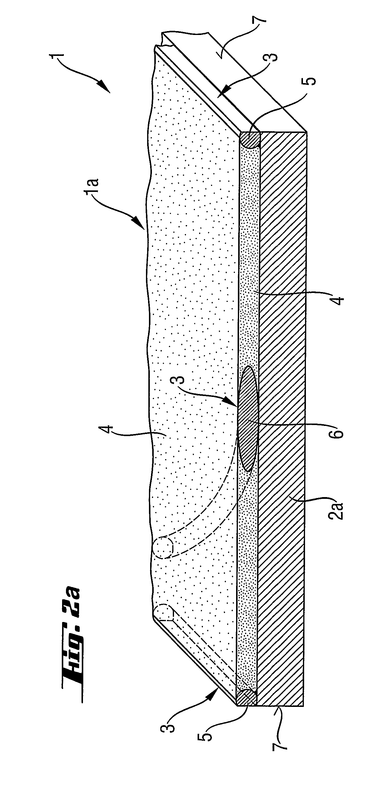
[0096]FIG. 2b shows a third embodiment in the perspective cross section view. The area between the edge wires 3, 5 is completely filled with intermediate wires 6. All wires 5 and 6 are parallel to one another and the spaces between the wires are filled with soft material.

[0097]FIG. 3a shows a top view of a material strip according to the second embodiment of FIG. 2a comprising one intermediate wire 6 forming a regular wave that can contact the edge wires 5. The soft material 4 is partly shown for more clarity.

Example

[0098]In FIG. 3b an alternative fourth embodiment is shown where two intermediate wires 6 are arranged between the edge wires 5. The intermediate wires 6 contact one another in their apexes and their apexes also contact the edge wires 5. Another wire pattern is possible, where for examples the apexes don't contact one another (FIG. 3c). The soft material 4 is partly shown for more clarity.

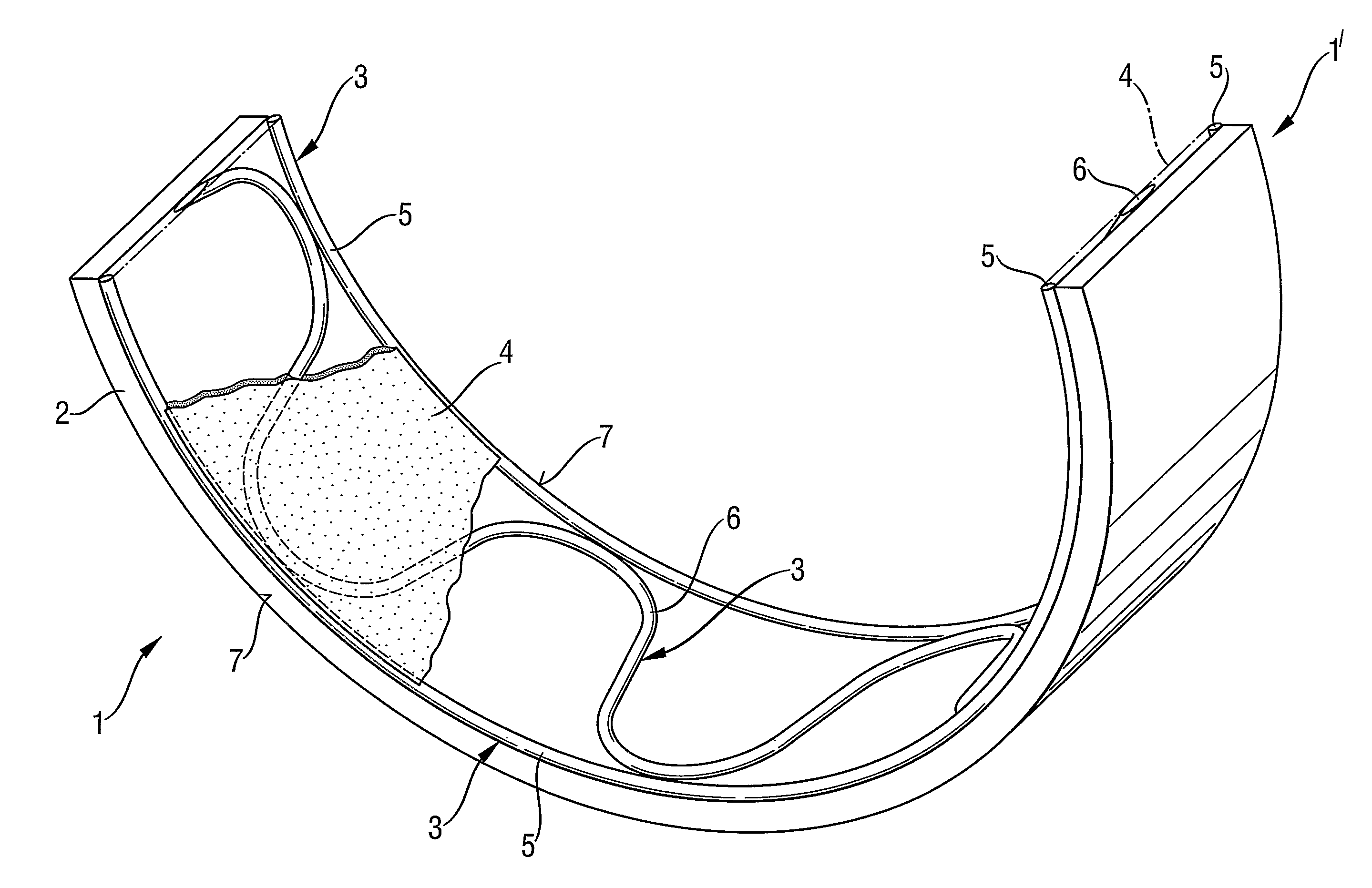
[0099]FIG. 4 shows the second embodiment of the inventive sliding bearing element as finished product in perspective illustration, whereby the element 1 is of the half-cylinder type 1′. The backing 2 coated with bearing alloy 3 in form of wires 5, 6 and soft material 4 is bent to a half-cylinder-shaped bearing 1. The wires being flush with opposite side edges of the backing and flush with the backing along their entire length so that there is no radial gap between the wires and the backing.

[0100]FIG. 5 illustrates a fourth embodiment of the sliding bearing element as a bushing 1″ in perspective ill...


PUM

PropertyMeasurementUnit
Percent by massaaaaaaaaaa

Abstract

A sliding bearing element is characterized in that a bearing material that is bonded to the backing is disposed at least at the edges of the backing in form of wires in the circumferential direction and that a soft material is located at least in a space between said wires. At least one intermediate wire can be disposed between the two edge wires generally running in the circumferential direction. The method comprises the following processing steps: providing a strip of steel or any other material having the required degree of strength which forms the backing of the bearing to be produced, bonding at least one wire at each of the two edges of the backing strip, whereat disposing the wires in such a manner that said wires run in circumferential direction generally, and filling out the spaces between the wires with soft material.

Description

BACKGROUND OF THE INVENTION[0001]1. Technical Field[0002]The invention relates to a sliding bearing element comprising a backing, especially made of steel, said backing is lined with a bearing material and a soft material, wherein the bearing material is capable of sustaining a bearing load and the soft material is of anti-seizure quality. Within the scope of the present invention the slide bearing can consist Of two half cylinders or the slide bearing is a bush. So that the sliding bearing element is either a half cylinder (half-cylinder type) or the element is a bush (bush-type).[0003]2. Related Art[0004]Such sliding bearing elements are used as oil lubricated crankshaft bearings in internal combustion engines. In this case each bearing comprises two half cylinders clamped together in the big end of the connecting rod—the rod bearing or big end bearing—or the cylinder block and a retaining cap—main bearing.[0005]It has been found that the good load sustaining qualities of the bear...

Claims


Application Information

Patent Timeline
IPC IPC(8): B32B3/02F16C17/00F16C9/00F16C9/02F16C9/04F16C33/12F16C33/20F16C33/24F16C33/28
CPCF16C9/00F16C33/24F16C33/28Y10T428/12681Y10T428/12722Y10T428/12569Y10T428/12715Y10T428/12396Y10T428/12486Y10T428/12535
Inventor PRATT, GEORGE
Owner FEDERAL MOGUL WIESBADEN
Why Eureka
Try Eureka