Modular Electrical System and Method for its Operation

Active Publication Date: 2010-02-04
SIEMENS AG
View PDF7 Cites 1 Cited by
  • Summary
  • Abstract
  • Description
  • Claims
  • Application Information

AI Technical Summary

Benefits of technology

[0022]If, in a next method step, the two-wire line is connected to a primary module, and the differential voltage is evaluated in the primary module for the purpose of detecting an overload of the system, a flexible response to a potential overloading of the system can be implemented for example by means of the generation of diagnostic or system alarms and measures can be taken to avoid a system failure.
[0025]According to the method it is advantageous if, following activation of the system, a second ratio is used for monitoring an overload, the second ratio being selected greater than the first ratio in order to minimize the risk of an incorrect decision due to faults on the two-wire line. If, on the basis of the differential voltage, the second ratio assumes a value of, for example, 1.2, which represents a temporary overload of 20%, the primary module can tolerate this for a short time with a corresponding evaluation unit and respond with a corresponding generation of fault messages or diagnostic alarms only if the overload persists for a longer period. Temporary faults which can lead to the differential voltage being distorted can be caused by EMC interference, for example. Said EMC malfunctions are produced, for example, due to noise signals being coupled-in, which noise signals are possibly generated as a result of the connection of electrical loads which are located in the vicinity of the two-wire lines. Accordingly, said method and also the above-described system with its two-wire line will be used advantageously in EMC-contaminated environments comprising spatially distributed components. In contrast, with power balancing according to the prior art with a single-wire line, extreme deviations in the corresponding measured values would be likely in the case of EMC interference, which would fundamentally call into question the procedure according to the method of power balancing according to the prior art.

Problems solved by technology

During operation of the automation system, unpredictable spontaneous failures of the power supply subassemblies can occur both during the startup of the subassemblies and during operation, the spontaneous failures being caused due to the current-consuming subassemblies not being matched in terms of their power requirements to the current-emitting subassemblies.
If the available power is, for example, only slightly less in this case than the maximum required power, it can happen that an automation system initially operates totally without problems, but fails during operation due to apparently random environmental parameters.
This failure can possibly occur only after a relatively long period of trouble-free operation.
1. A system “powers up” apparently normally, but crashes spontaneously when all the peripheral subassemblies have been activated.
2. A system “powers up” apparently normally, but crashes spontaneously after reaching its operating temperature.
3. A system “powers up” normally, runs correctly for years, for example, but crashes spontaneously when a further peripheral subassembly is plugged in.
In the aforementioned cases there is an overload which often remains initially undetected by the automation system.
A disadvantage with this system is that only the action of plugging in further individual modules is taken into account with regard to the total power requirements.
If, for example, an additional power supply module is added to the system, this cannot be taken into account for calculating a power ratio between the current-consuming and the current-emitting modules.

Method used


Image

  • Modular Electrical System and Method for its Operation
  • Modular Electrical System and Method for its Operation
  • Modular Electrical System and Method for its Operation

Examples


Embodiment Construction

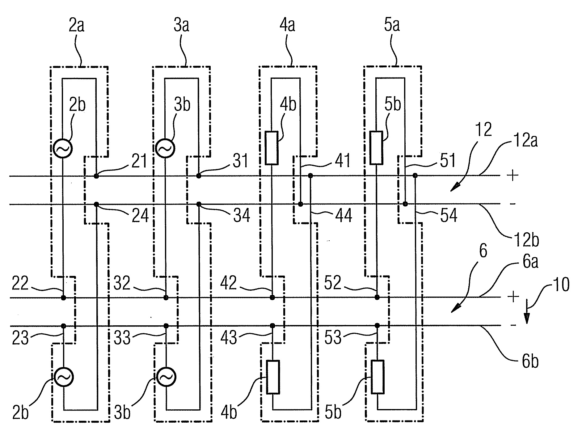
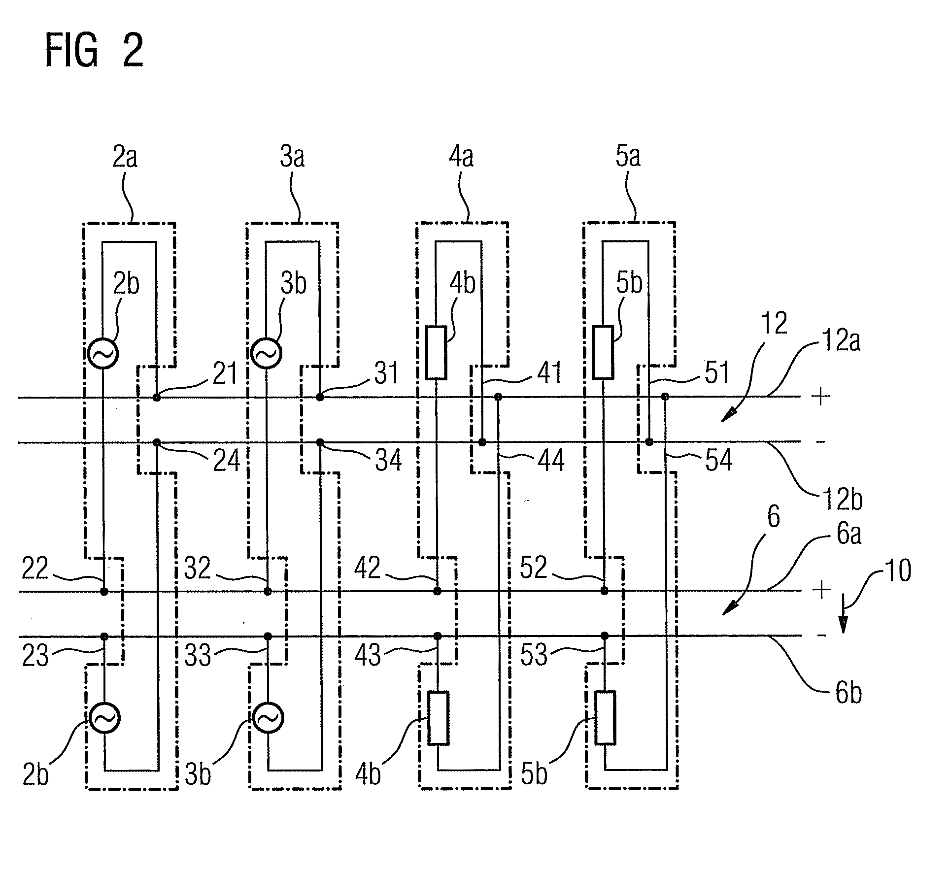
[0029]FIG. 1 shows a modular electrical system 1. In this arrangement the system 1 has a first source module 2, a second source module 3, a first sink module 4 and a second sink module 5 as pluggable subassemblies on a backplane structure, which in combination with a primary module 7 form an automation system.

[0030]A two-wire line 6 having a first conductor 6a and a second conductor 6b, embodied as a two-wire bus, runs through the entire automation system, starting from the primary module 7 and continuing via the modules 2, . . . ,5. In order to connect to the two-wire line the first source module 2 has a first source identification means 2a and the second source module 3 has a second source identification means 3a. The source identification means 2a,3a of the source modules 2,3 represent the power that is available by way of the source modules 2,3. A first sink identification means 4a that is available in the first sink module 4 and a second sink identification means 5a that is ava...


PUM


Abstract

A modular electrical system including a first current-emitting source module and a first current-consuming sink module which is connected to the first current-emitting source module is provided. The first sink module has a first sink identification means to identify maximum power requirement of the first sink module. The object of providing power balancing between a first source module and a first sink module is achieved in that the first source module has a first source identification means for identifying the power capacity of the first source module, wherein in order to calculate a power ratio of the system the first sink identification means and the first source identification means are connected to a two-wire line for the purpose of generating a differential voltage.

Description

CROSS REFERENCE TO RELATED APPLICATIONS[0001]This application claims priority of European Patent Office application No. 08013764.9 EP filed Jul. 31, 2008, which is incorporated by reference herein in its entirety.FIELD OF INVENTION[0002]The invention relates to a modular electrical system having a first current-emitting source module and a first current-consuming sink module that is connectable thereto, wherein the first sink module has a first sink identification means for identifying its maximum power requirement.[0003]The invention also relates to a method for operating a modular electrical system of said kind.BACKGROUND OF INVENTION[0004]In modular electrical systems, such as for example in the case of a modularly constructed automation system, it is common practice to arrange different automation technology subassemblies on a backplane structure or a simple mounting rail and to interconnect them electrically. Said different subassemblies can then be basically distinguished acco...

Claims


Application Information

Patent Timeline
IPC IPC(8): G01R31/08
CPCH02J1/14H02J1/10
Inventor ABERT, MICHAELENGL, WERNERGRIESSBACH, GUNTERHIRMER, GERALDKLAMM, ARNOLDMETZLER, MATTHIASSCHMIDT, DIRK
Owner SIEMENS AG
Why Eureka
Try Eureka