Al technical title is built by PatSnap Al team. It summarizes the technical point description of the patent document.
a balloon catheter and occlusion device technology, applied in the field of balloon catheter occlusion device and methods of use, can solve the problems of affecting the operation of the balloon catheter, so as to achieve the effect of stabilizing the position of the balloon catheter during expansion
Inactive Publication Date: 2005-11-22
EDWARDS LIFESCIENCES CORP
View PDF18 Cites 36 Cited by
Summary
Abstract
Description
Claims
Application Information
AI Technical Summary
This helps you quickly interpret patents by identifying the three key elements:
Problems solved by technology
Method used
Benefits of technology
[0015]In one embodiment, the device includes a substantially rigid cannula adapted to enter the aorta with a proximal end that receives cardioplegia solution into a cardioplegia lumen and delivers it to an infusion port in the distal region of the cannula. An occluder, mounted on the distal region of the cannula, expands away from the cannula upon activation to substantially occlude the aorta downstream from the infusion port. During use, the occluder isolates the ascending aorta from the peripheral vasculature. The substantially rigid nature of the cannula inhibits migration of the occluder into the ascending aorta, thus overcoming problems associated with other currently available aortic balloon cannulas. In cer
Problems solved by technology
Each of the existing methods of blocking aortic blood flow and arresting the heart carries with it some undesired aspects.
However, the physical clamping action on the vessel has been linked to many adverse body responses.
In addition, the potential for vascular damage, like aortic dissections, may also incur during the clamp application.
The percutaneous balloon catheter occluder has a distinct drawback in that it must be placed with visionary assistance.
This added equipment is not always readily available in the surgical suite.
In addition, the catheter placement up to the aorta may also create additional vascular trauma and emboli g
Method used
Image
Click on the blue label to locate the original text in one second.
Reading with bidirectional positioning of images and text.
Examples
Embodiment Construction
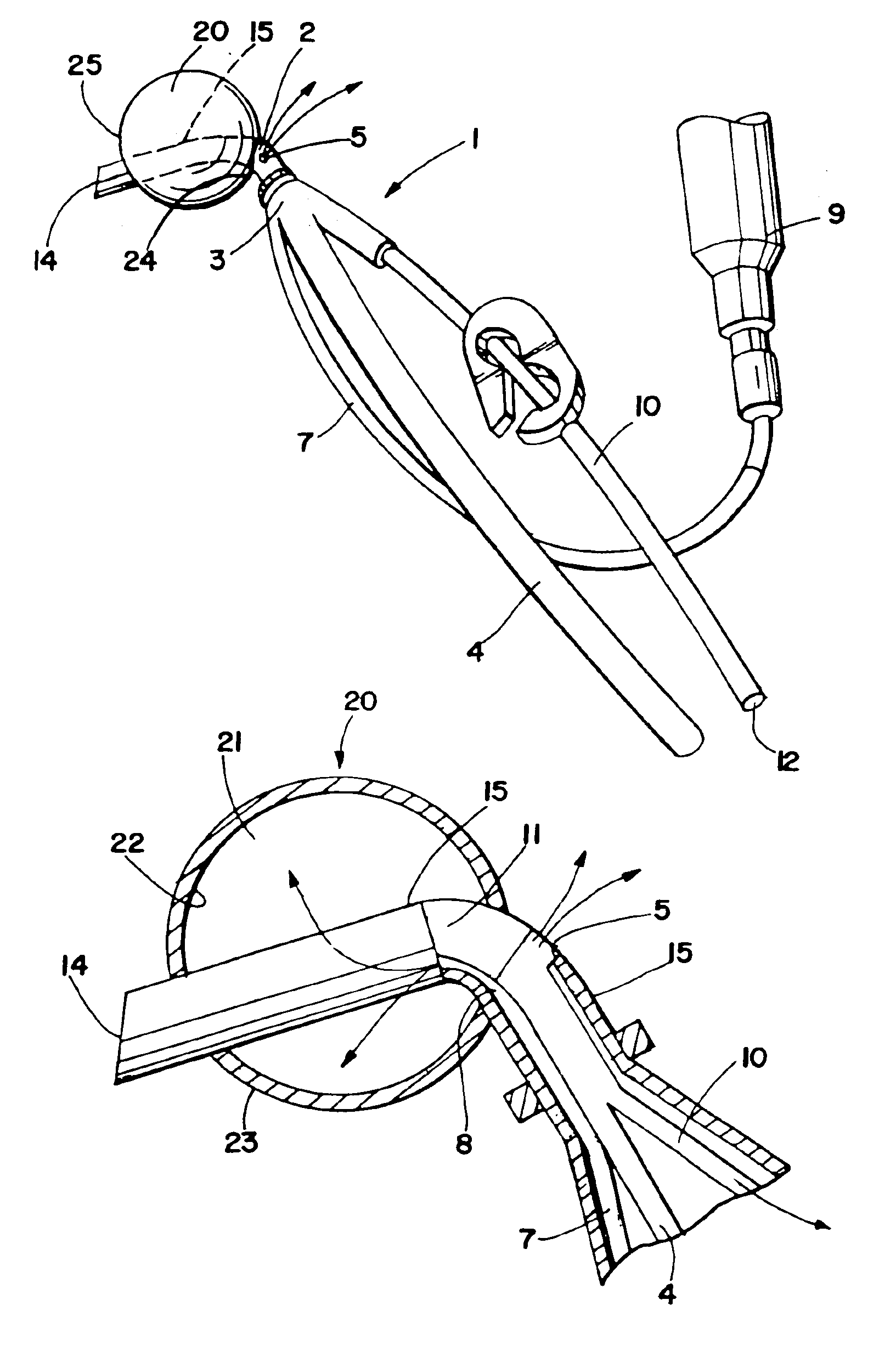
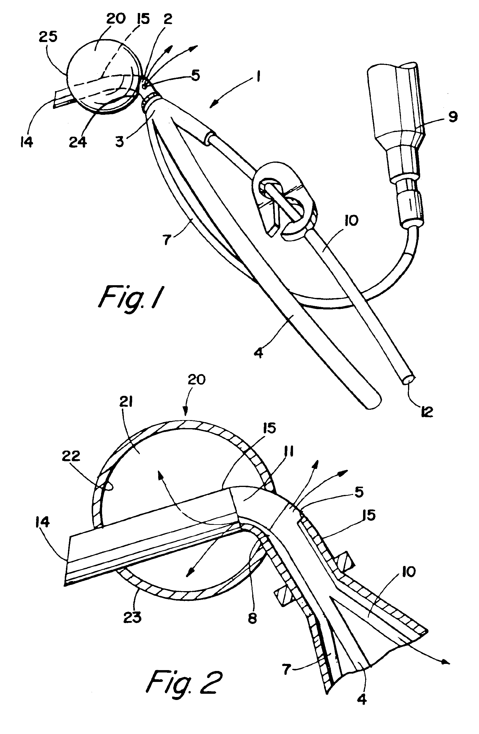
[0081]FIG. 1 depicts an embodiment of a cardioplegia occluder 1 for delivering cardioplegia to the aorta during cardiopulmonary bypass where the distal region 2 of the substantially rigid cannula 3 is curved to facilitate self-centering inside the aorta. The distal end of the cannula 14 is adapted to enter the aorta.
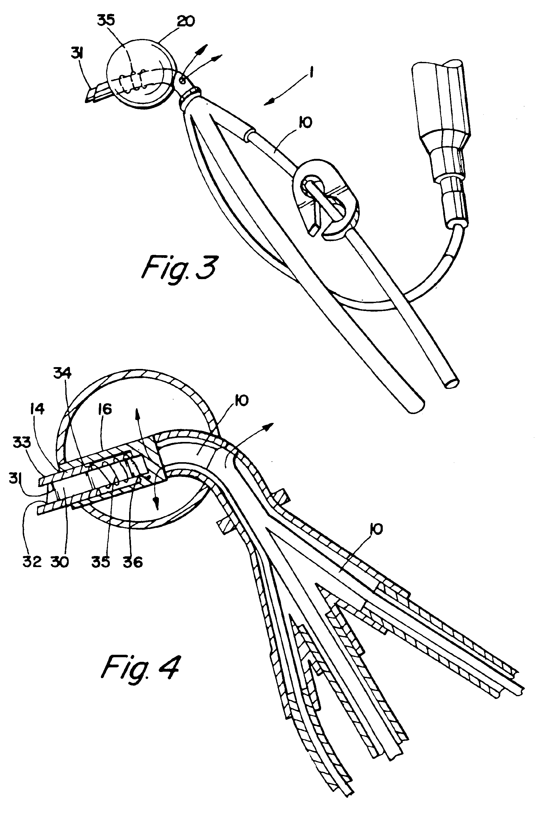
[0082]In this embodiment, a spherical occluder 20 is circumferentially disposed about the outer surface 15 of the distal region of the cannula forming a chamber 21 with an inner surface 22, an outer surface, a proximal end 24 and a distal end. In some embodiments, the occluder is an inflatable balloon. In other embodiments, the balloon is foam-filled, so that the occluder may be inserted in a contracted condition, for instance, within a sleeve or under negative pressure, and when released from the sleeve or the negative pressure, will automatically expand to the predetermined shape. Although FIG. 1 and FIG. 2 depict the occluder as spherical, in other embodiments, it is ...
PUM
Abstract
A cardioplegia occluder and methods of using the device during cardiac surgery are disclosed. The system typically includes a substantially rigid cannula with an occluder mounted on the distal region of the cannula that expands upon activation to occlude the aorta downstream of an infusion port which delivers cardioplegia solution to arrest the heart. Systems including cutting blades, blade guards, flanges, radiopaque markers and occluder aligners are also disclosed. In use, the distal end of the cannula is inserted through an incision into the aorta, the occluder is expanded and cardioplegia solution is infused upstream of the aorta to arrest the heart. The infusion port can alternately be used to aspirate cardioplegia or embolic debris or other unwanted material from the aorta.
Description
[0001]This is a continuation of U.S. application Ser. No. 09 / 387,634, filed Aug. 31, 1999, now U.S. Pat. No. 6,176,851, which is a continuation of U.S. application Ser. No. 08 / 993,202, filed Dec. 18, 1997, now U.S. Pat. No. 6,048,331, which is a continuation-in-part of U.S. application Ser. No. 08 / 854,806, filed May 12, 1997, now U.S. Pat. No. 6,231,544, which is a continuation-in-part of U.S. application Ser. No. 08 / 645,762, filed May 14, 1996, now abandoned. The contents of these prior applications are expressly incorporated herein by reference in their entirety.FIELD OF THE INVENTION[0002]This invention relates to methods and apparatus for administering cardioplegia to the aorta during cardiac surgery. The devices include a cardioplegia occluder that can include various features such as a cutting blade, a blade guard, a flange, radiopaque markers and an occluder aligner to properly position the distal end of the device within the aorta. Once the cardioplegia occluder is in its pr...
Claims
Application Information
Patent Timeline
Application Date:The date an application was filed.
Publication Date:The date a patent or application was officially published.
First Publication Date:The earliest publication date of a patent with the same application number.
Issue Date:Publication date of the patent grant document.
PCT Entry Date:The Entry date of PCT National Phase.
Estimated Expiry Date:The statutory expiry date of a patent right according to the Patent Law, and it is the longest term of protection that the patent right can achieve without the termination of the patent right due to other reasons(Term extension factor has been taken into account ).
Invalid Date:Actual expiry date is based on effective date or publication date of legal transaction data of invalid patent.