Multi-mode electromagnetic target discriminator sensor system and method of operation thereof

a sensor system and electromagnetic target technology, applied in the field of metal detection sensor system, can solve the problems of prior art metal detectors not addressing the problems of small and large metal non-mine objects (clutter) commonly found in the environment, and the small and large metal non-mine objects are a major complication

Active Publication Date: 2005-11-22
THE JOHN HOPKINS UNIV SCHOOL OF MEDICINE
View PDF4 Cites 106 Cited by
  • Summary
  • Abstract
  • Description
  • Claims
  • Application Information

AI Technical Summary

Problems solved by technology

However, small and large metal non-mine objects (clutter) commonly found in the environment are a major complication in mine detection because they represent false targets.
Prior art metal detectors do not address the operation of a metal detector for both time multiplexed TD and FD modes with the antenna (transmitter and receiver coils) optimized for metal detection and target classification under all soil conditions.

Method used


Image

  • Multi-mode electromagnetic target discriminator sensor system and method of operation thereof
  • Multi-mode electromagnetic target discriminator sensor system and method of operation thereof
  • Multi-mode electromagnetic target discriminator sensor system and method of operation thereof

Examples


second embodiment

[0036]FIG. 9 is a block diagram of the METD sensor with analog FD mode operation.

[0037]FIG. 10 is an operational flow chart of the METD system.

[0038]FIG. 11 is diagram of a METD sensor with digital FD mode operation.

[0039]FIG. 12 is a diagram of a METD FD and TD data classification algorithm.

[0040]FIG. 13 is a simplified view of conical detection region as function of depth of non-overlapping metal detectors.

[0041]FIG. 14 is a diagram of a METD sensor array with 3 differential antennas.

[0042]FIG. 15 is a block diagram of a METD sensor array with 2 differential antennas.

[0043]FIG. 16 is a block diagram of the METD system on a surrogate robotic platform (SRP) according to another embodiment of the present invention.

DETAILED DESCRIPTION OF THE PREFERRED EMBODIMENTS

[0044]Preferred embodiments of the present invention will be described in detail herein below with reference to the accompanying drawings. In the following description of the present invention, a detailed description of known...

first embodiment

[0045]the present invention includes at least a combined time-domain (TD) and frequency-domain (FD) metal detector and target classification algorithm (TCA) that utilizes the best features of both electromagnetic induction (EMI) technologies for metal target detection and discrimination. This multi-mode electromagnetic target discriminator (METD) sensor utilizes automatic ground balance technique and void detection capability of the electromagnetic target discriminator (EDT) described in Carl V. Nelson, Charles B. Cooperman, Wolfger Schneider, Douglas S. Wenstrand and Dexter G. Smith, “Wide Bandwidth Time-domain Electromagnetic Sensor for Metal Target Classification,” IEEE TGARS, Vol. 39, No. 6, pp 1129–1138, June 2001; Carl V. Nelson and Toan B. Huynh, “Wide Bandwidth, Time Decay Responses from Low-metal Mines and Ground Voids,” SPIE, FL, 2001. Proceeding of SPIE AeroSense 2001 Conference, Detection and Remediation Technologies for Mines and Minelike Targets, Orlando, Fla., 16–20 A...


PUM


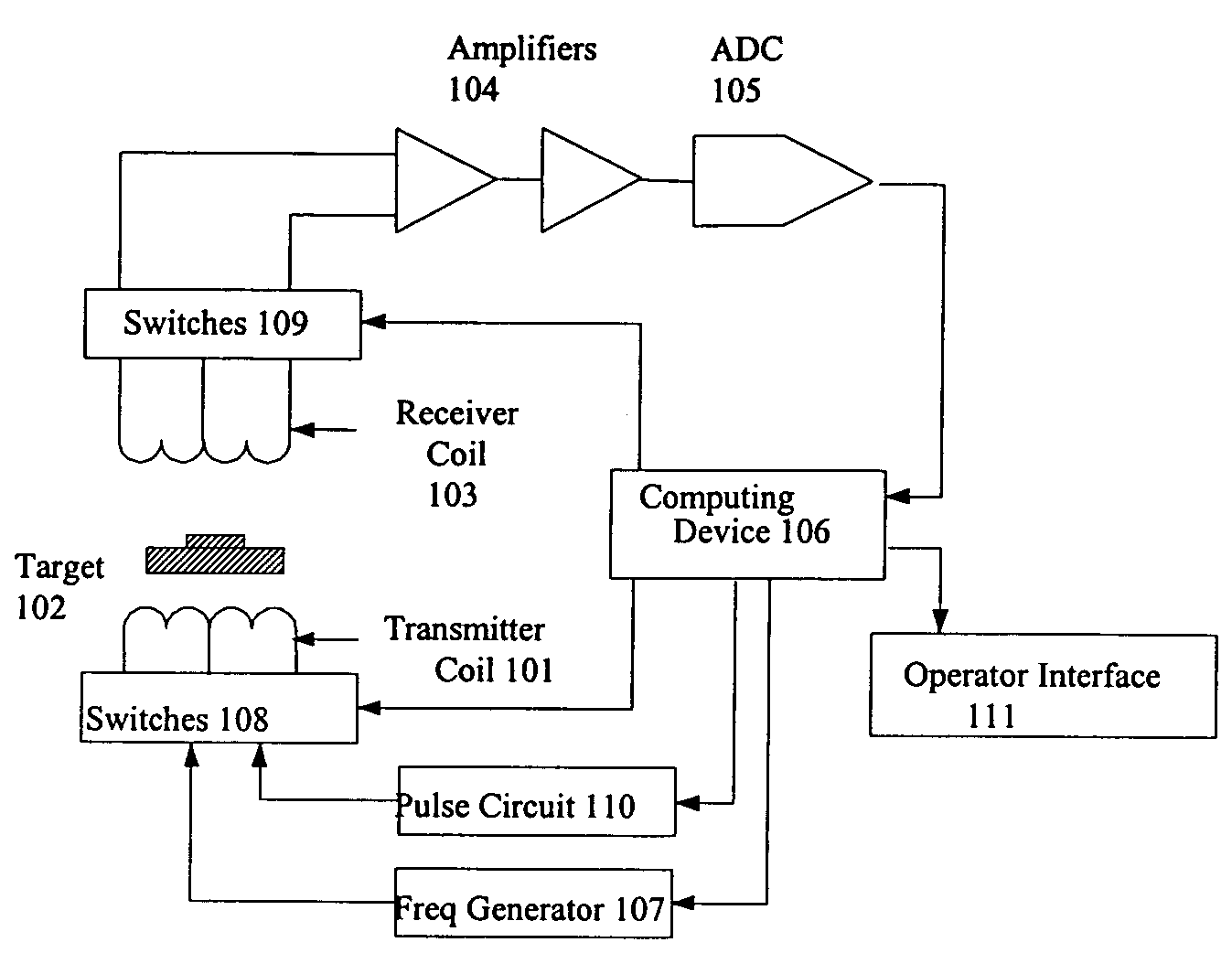
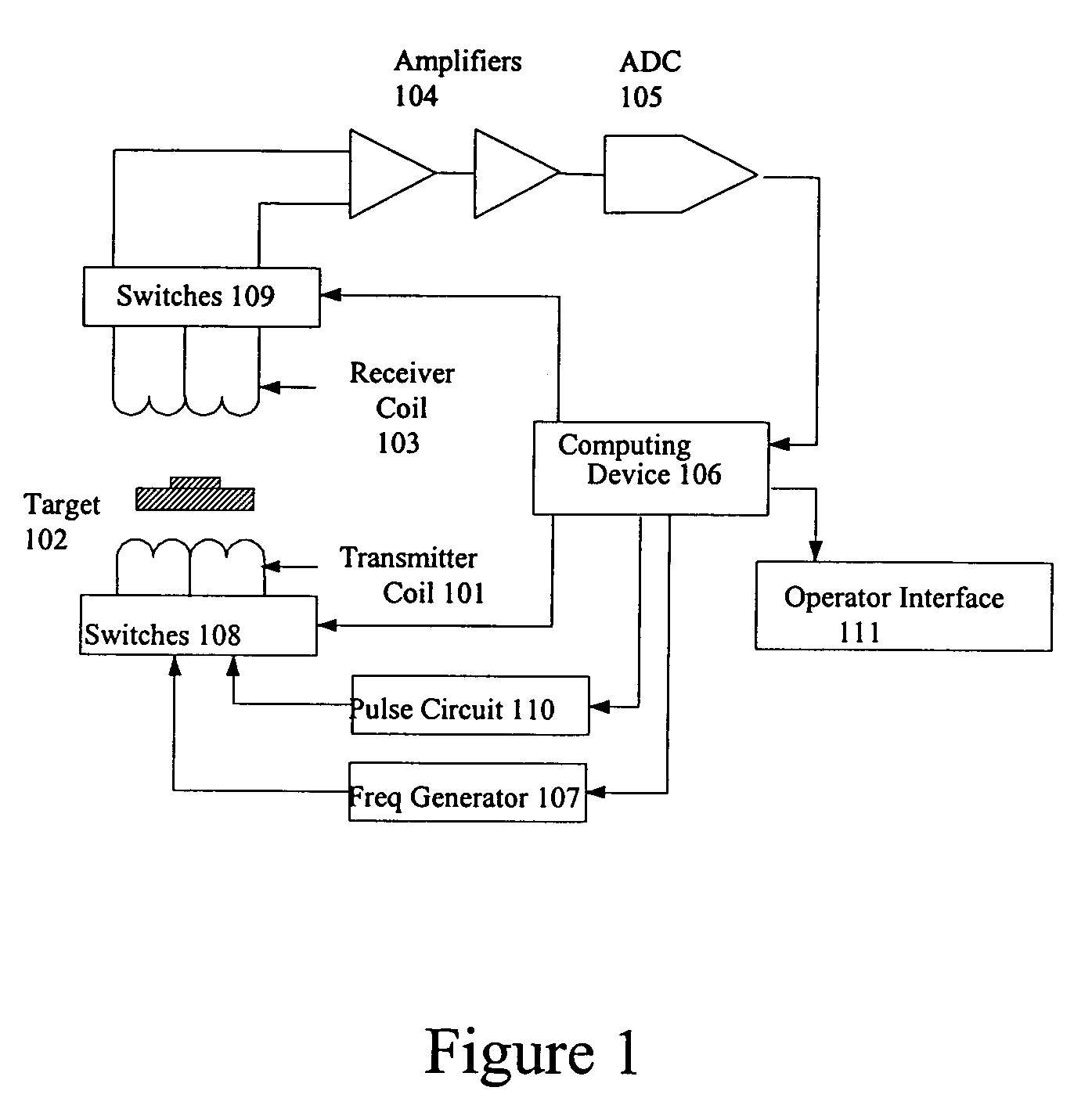
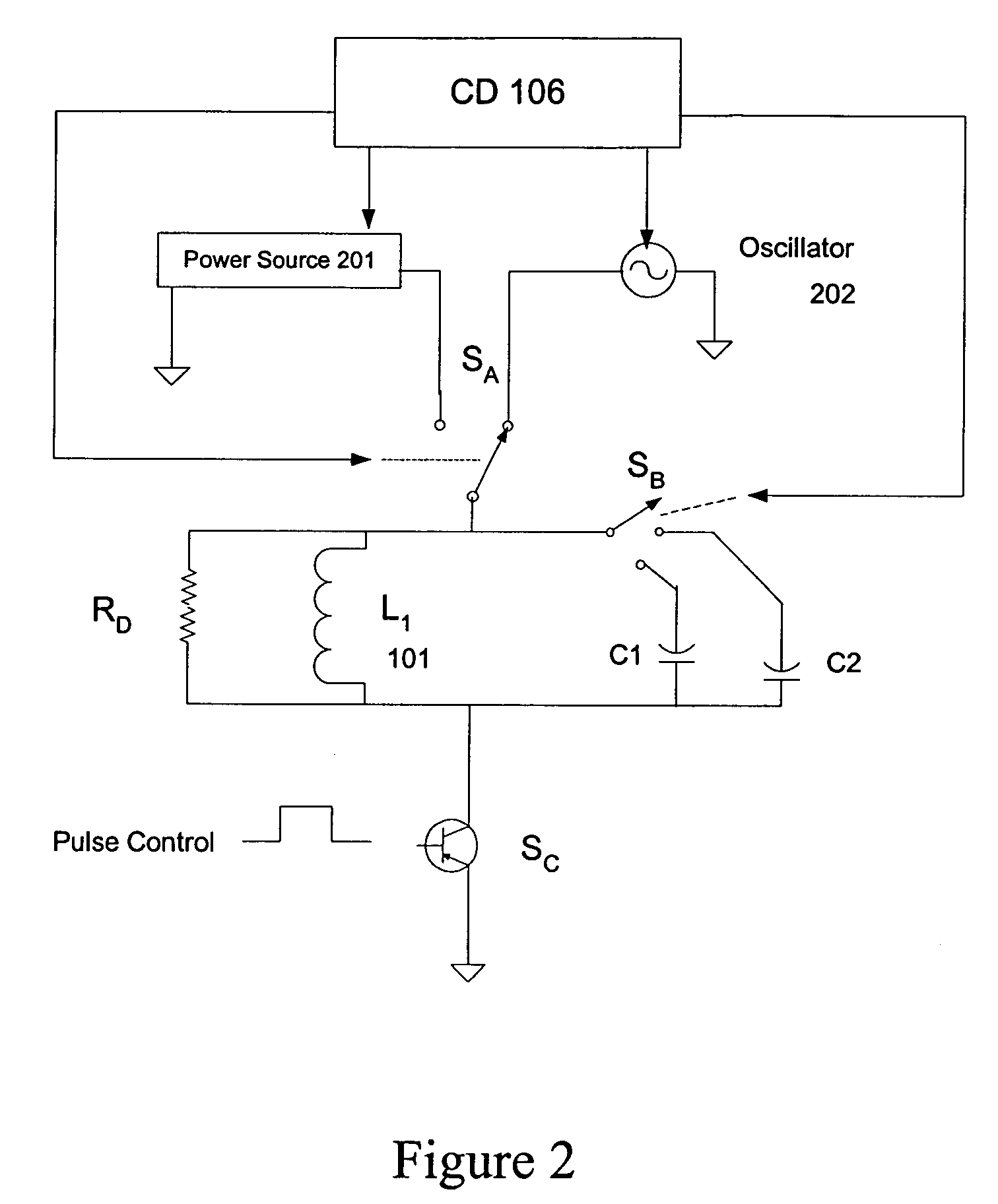
Abstract

A multi-mode electromagnetic target discrimination sensor system for transmitting an electromagnetic signal and receiving a reflected signal from at least one target is disclosed having a variable inductance antenna having a variable inductance transmitter and a variable inductance receiver for varying at least one of operating bandwidth, sensitivity and size of the antenna, a processor for alternating between a time domain operating mode and a frequency domain operating mode, and controlling the variation of the inductance of the variable inductance antenna based on a current operating mode, and at least one processing algorithm for receiving signals from the receiver, discriminating targets from the received signals, and outputting the discrimination results is disclosed.

Description

CROSS-REFERENCE TO RELATED APPLICATIONS[0001]This application claims the benefit of U.S. Provisional Application No. 60 / 441,431, filed Jan. 21, 2003, the contents of which are incorporated herein by reference.STATEMENT OF GOVERNMENTAL INTEREST[0002]This invention was made with Government support under U.S. Army Contract No. DAAB15-00-C-1008. The Government has certain rights in the invention.BACKGROUND OF THE INVENTION[0003]1. Field of the Invention[0004]The present invention generally relates to a multi-mode electromagnetic target discrimination sensor system and method of operation thereof. More particularly, the present invention relates to a metal detection sensor system that operates in both time and frequency domain modes.[0005]2. Description of the Related Art[0006]Current state-of-the-art electromagnetic induction (EMI) metal detectors can detect the small amount of metal in plastic-cased land mines at shallow depths under a wide range of environmental and soil conditions. H...

Claims


Application Information

Patent Timeline
Patent Type & Authority Patents(United States)
IPC IPC(8): G08B13/18G08B13/24F41H11/16G01V3/10
CPCF41H11/136F41H11/16G01V3/104
Inventor NELSON, CARL V.
Owner THE JOHN HOPKINS UNIV SCHOOL OF MEDICINE
Why Eureka
Try Eureka