Active optical system for changing the wavelength of an image

a technology of active optical system and image, applied in the field of active optical system, can solve the problems of signal processing bottlenecks, reduced speed, mismatch between the actual wavelength of an image and the wavelength required, etc., and achieve the effect of the overall system bandwidth

Inactive Publication Date: 2005-11-22
THE BOEING CO
View PDF10 Cites 3 Cited by
  • Summary
  • Abstract
  • Description
  • Claims
  • Application Information

AI Technical Summary

Benefits of technology

[0011]The present system produces copies of the input signal image intensity at a different wavelength. The device works in a manner that allows direct optical to optical translation, without having to change the signal into an electronic incarnation. This invention allows converting the wavelength to one within the desired band while the signal remains in an optical state. With a direct optical to optical translation, bottlenecks do not form and the bandwidth of the overall system is not affected by the wavelength changing hardware.

Problems solved by technology

Unfortunately, due to optical hardware constraints such as laser output wavelength, optimum optical fiber transmission wavelength, etc., there are frequently mismatches between an image's actual wavelength and the wavelength required for operation in a certain optical device.
This causes signal processing bottlenecks, reduced speed, reduced bandwidth as well as increased size, weight, volume and complexity of the associated optical hardware.

Method used


Image

  • Active optical system for changing the wavelength of an image
  • Active optical system for changing the wavelength of an image

Examples


Embodiment Construction

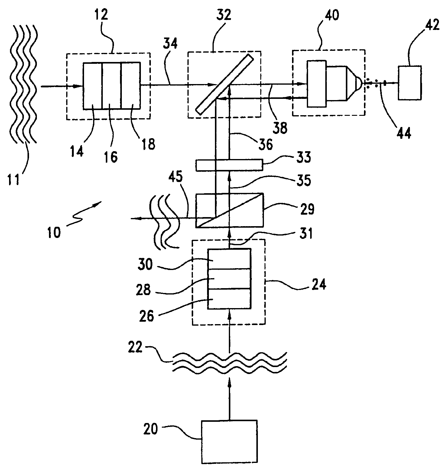
[0014]Referring to the drawings and the characters of reference marked thereon FIG. 1 illustrates a preferred embodiment of the present invention, designated generally as 10. An incoming optical image 11 is received by a first control optics assembly, designated generally as 12 The image of an optical beam is generally described as the contour of constant phase over the physical cross-section of the beam. Although any optical source will have a phase associated with it, in most cases, sources will be objects that are being imaged or will be from transmitters of digitally encoded optical beams. The first control optics assembly 12 adjusts the incoming optical image 11 in accordance with desired wavelength and beam propagation parameters. These parameters could include, for example, precise wavelength filtering to the expected signal wavelength, the optical bandwidth of the incoming signal, or the polarization of the light. The wavelength may be controlled to fit within the detection ...


PUM

PropertyMeasurementUnit
wavelengthsaaaaaaaaaa
wavelengthaaaaaaaaaa
diameteraaaaaaaaaa

Abstract

A first control optics assembly receives an incoming optical image. A template optical element produces a template optical intensity profile. A second control optics assembly receives the template optical intensity profile. A polarization separator receives an output from the second control optics. A quarter wave plate changes the polarization of the polarized output therefrom. A combiner receives an output from the first control optics assembly and an output from the quarter wave plate and provides a combined, co-linear propagation output image having an initial beam size. An SLM provides absorption of a portion of the combined output image which changes the local index of refraction of the SLM so that the local reflection at the template optical intensity profile changes. The template optical intensity profile reproduces the image of the absorbed portion as an outgoing image that is reflected back through a portion of the system providing a converted image having substantially the same intensity pattern as the incoming optical image but a different wavelength.

Description

CROSS-REFERENCE TO RELATED APPLICATION[0001]This is a Continuation of U.S. application Ser. No. 10 / 139,011, filed on May 3, 2002, which will issue as U.S. Pat. No. 6,819,476 on Nov. 16, 2004.BACKGROUND OF THE INVENTION[0002]1. Field of the Invention[0003]This invention relates to active optical systems and more particularly to an active optical system for changing the wavelength of an incoming optical image.[0004]2. Description of the Related Art[0005]Frequently, in opto-electronic applications, devices exist that require inputs within a certain wavelength band. Unfortunately, due to optical hardware constraints such as laser output wavelength, optimum optical fiber transmission wavelength, etc., there are frequently mismatches between an image's actual wavelength and the wavelength required for operation in a certain optical device. Typically, converting an image (or two-dimensional signal array) from one wavelength to another requires changing the optical signal to an equivalent e...

Claims


Application Information

Patent Timeline
Patent Type & Authority Patents(United States)
IPC IPC(8): G02F2/00G02F2/02
CPCG02F2/02
Inventor HUNT, JEFFREY H.
Owner THE BOEING CO
Why Eureka
Try Eureka