Servo writing a disk drive from spiral tracks by generating a time-stamped sync mark detect signal processed by timing recovery firmware

a technology of timing recovery firmware and disk drive, which is applied in the direction of recording signal processing, maintaining head carrier alignment, instruments, etc., can solve the problems of complex timing circuitry, high cost of external servo writers, and inability to detect signals in time-stamped sync marks

Active Publication Date: 2005-11-22
WESTERN DIGITAL TECH INC
View PDF21 Cites 187 Cited by
  • Summary
  • Abstract
  • Description
  • Claims
  • Application Information

AI Technical Summary

Benefits of technology

[0011]The present invention may also be regarded as s disk drive comprising a head disk assembly (HDA) comprising a disk, an actuator arm, a head connected to a distal end of the actuator arm, and a voice coil motor for rotating the actuator arm about a pivot to position the head radially over the disk. The disk comprising a plurality of spiral tracks, wherein each spiral track comprises a high frequency signal interrupted at a predetermined interval by a sync mark. The head internal to the disk drive is used to read the spiral tracks to generate a read signal. The read signal is processed with sync mark detection circuitry to detect the sync marks in the spiral tracks. A time-stamped sync mark detect signal is generated when one of the sync marks is detected, wherein the time-stamped sync mark detect signal represents a time when the sync mark was detected relative to a servo write clock. A difference between the time-stamped sync mark detect signal and an expected time is computed in firmware to generate a coarse timing recovery measurement used to synchronize the servo write clock. The servo write clock and the head internal to the disk drive are used to write the product servo sectors along a substantially circular target path.

Problems solved by technology

However, external servo writers are expensive and require a clean room environment so that a head positioning pin can be inserted into the head disk assembly (HDA) without contaminating the disk.
Thus, external servo writers have become an expensive bottleneck in the disk drive manufacturing process.
However, in the '679 patent the timing recovery measurement for updating the PLL is generated in hardware using complex and expensive timing circuitry for measuring the phase difference between the detected missing bits and the servo write clock.

Method used


Image

  • Servo writing a disk drive from spiral tracks by generating a time-stamped sync mark detect signal processed by timing recovery firmware
  • Servo writing a disk drive from spiral tracks by generating a time-stamped sync mark detect signal processed by timing recovery firmware
  • Servo writing a disk drive from spiral tracks by generating a time-stamped sync mark detect signal processed by timing recovery firmware

Examples


Embodiment Construction

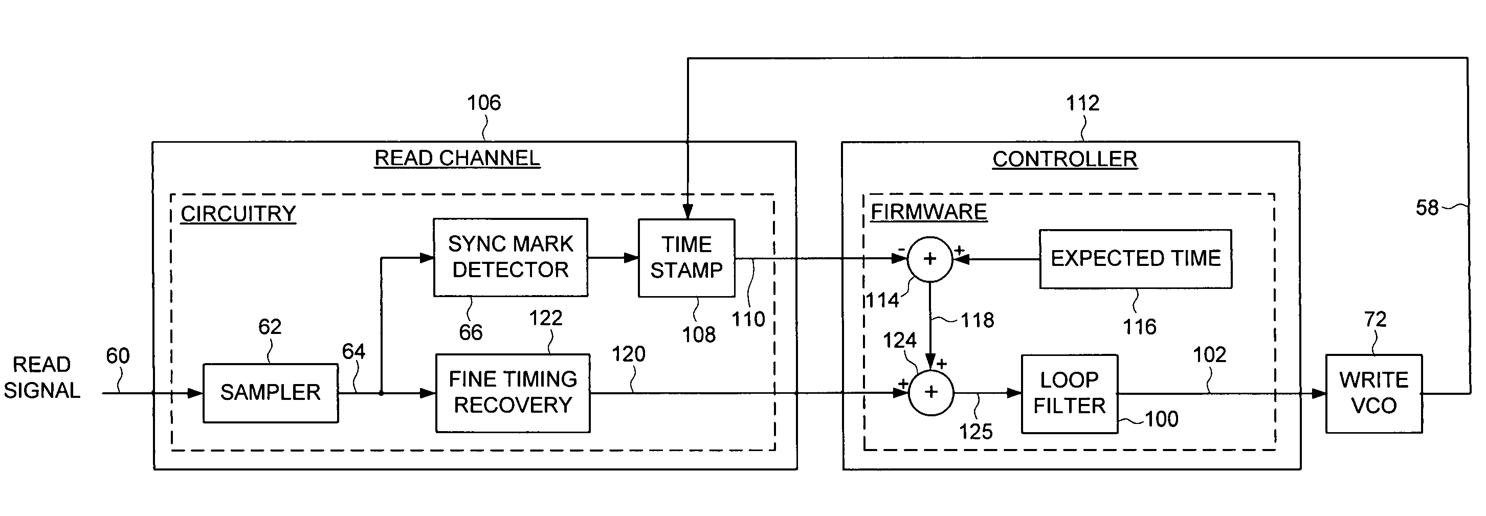
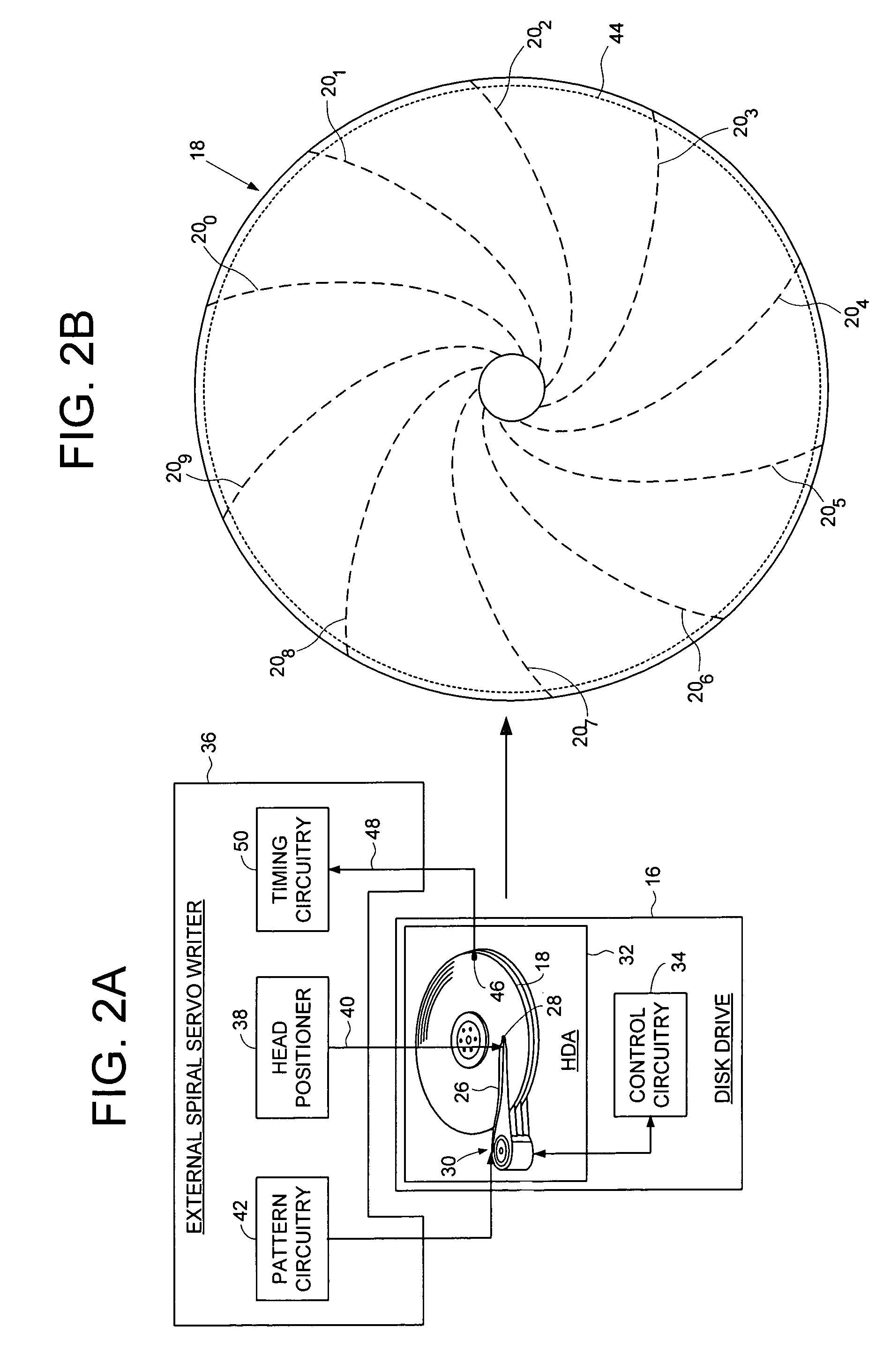
[0026]FIGS. 2A and 2B show a disk drive 16 according to an embodiment of the present invention comprising a disk 18 having a plurality of spiral tracks 200–20N, wherein each spiral track 20 comprises a high frequency signal 22 interrupted at a predetermined interval by a sync mark 24 (FIG. 3B). The disk drive 16 further comprises an actuator arm 26, a head 28 connected to a distal end of the actuator arm 26, and a voice coil motor 30 for rotating the actuator arm 26 about a pivot to position the head 28 radially over the disk 18. The head 28 internal to the disk drive 16 is used to read the spiral tracks 200–20N to generate a read signal. The read signal is processed with sync mark detection circuitry to detect the sync marks 24 in the spiral tracks 200–20N. A time-stamped sync mark detect signal is generated when one of the sync marks is detected, wherein the time-stamped sync mark detect signal represents a time when the sync mark was detected relative to a servo write clock. A di...


PUM

PropertyMeasurementUnit
frequencyaaaaaaaaaa
FREQUENCYaaaaaaaaaa
outer diameteraaaaaaaaaa

Abstract

A disk drive is disclosed servo written from spiral tracks by generating a time-stamped sync mark detect signal processed by timing recovery firmware. A plurality of spiral tracks are written to the disk, wherein each spiral track comprises a high frequency signal interrupted at a predetermined interval by a sync mark. The head internal to the disk drive is used to read the spiral tracks, and a time-stamped sync mark detect signal is generated when one of the sync marks is detected. The time-stamped sync mark detect signal represents a time when the sync mark was detected relative to a servo write clock. A difference between the time-stamped sync mark detect signal and an expected time is computed in firmware to generate a coarse timing recovery measurement used to synchronize the servo write clock. The servo write clock and the head internal to the disk drive are used to write product servo sectors along a substantially circular target path.

Description

CROSS REFERENCE TO RELATED APPLICATIONS AND PATENTS[0001]This application is related to other co-pending U.S. patent applications including Ser. No. 10 / 769,387 entitled “USING AN EXTERNAL SPIRAL SERVO WRITER TO WRITE REFERENCE SERVO SECTORS AND SPIRAL TRACKS TO A DISK TO FACILITATE WRITING PRODUCT SERVO SECTORS TO THE DISK” filed on Jan. 30, 2004, Ser. No. 10 / 769,680 entitled “SERVO WRITING A DISK DRIVE BY SYNCHRONIZING A SERVO WRITE CLOCK TO A HIGH FREQUENCY SIGNAL IN A SPIRAL TRACK” filed on Jan. 30, 2004, and Ser. No. 10 / 769,386 entitled “SERVO WRITING A DISK DRIVE BY SYNCHRONIZING A SERVO WRITE CLOCK IN RESPONSE TO A SYNC MARK RELIABILITY METRIC” filed on Jan. 31, 2004, the disclosures of which are incorporated herein by reference.BACKGROUND OF THE INVENTION[0002]1. Field of the Invention[0003]The present invention relates to disk drives for computer systems. More particularly, the present invention relates to servo writing a disk drive from spiral tracks by generating a time-st...

Claims


Application Information

Patent Timeline
Patent Type & Authority Patents(United States)
IPC IPC(8): G11B5/09G11B5/596G11B27/30
CPCG11B5/59633G11B27/3027G11B2220/20
Inventor LEE, TEHRI S.
Owner WESTERN DIGITAL TECH INC
Why Eureka
Try Eureka