Multiple server in-rush current reduction

a server and in-rush current technology, applied in the field of rackmounted server systems, can solve the problems of complex power and frequency conditioning system, modem 42u server equipment racks consuming up to 20 kilowatts of power, and modern server footprints have decreased dramatically

Active Publication Date: 2005-11-22
HEWLETT-PACKARD ENTERPRISE DEV LP
View PDF9 Cites 51 Cited by
  • Summary
  • Abstract
  • Description
  • Claims
  • Application Information

AI Technical Summary

Problems solved by technology

While early server systems may have had multiple servers (or computers) in a single equipment rack, modern server footprints have decreased dramatically.
The power density “ceiling” only a few years ago was 1–3 kilowatts of power in a 42U rack; however, modem 42U server equipment racks consume up to 20 kilowatts of power.
A PDU may be as simple as a location within the rack-mounted server system to plug a set of standard 120 or 220 volt AC connectors, together with a breaker, or may be as complex as a power and frequency conditioning system.
Due to the large number of power cords, network cables, keyboard cables, video cables, mouse cables, and the like, it is very common that the PDUs of the related art are at best inconveniently accessible for resetting of any internal breakers, and are extremely inaccessible in the event they need to be replaced.
This feature of returning to previous operational states upon return of power after a loss of power, in combination with server density (which is ever-increasing), produces in-rush current problems.
Further consider that power to the rack-mounted system is lost due to an unscheduled event (electric utility failure, electrician opening wrong breaker, or the like), thus causing all forty-two servers to shut down.
In-rush currents associated with each of these servers simultaneously attempting to power-on, in the related art, can draw too much current for the power distribution system, including the PDUs.
Thus, in the related art system, one or more of the PDUs may trip their breakers, or worse, the current in-rush may damage a PDU.
In either case, the servers that receive power from the tripped or destroyed PDU are no longer operational.
As was discussed above, while it is possible to reset the breakers on the PDUs, this is not an easy or efficient task as it requires a person to physically access the breaker to reset it.
Moreover, replacing the PDUs may disable the rack-mounted server system for many hours or even days.
During this short period of time, a large amount of current is drawn by the power supply to charge these capacitors causing a current surge at the power supply line cord input.
Additionally, electric motors, for example fan motors, have start up current requirements that far exceed their steady state current draw.
While laws may require certain safety margins to be followed when sizing circuit wiring and breakers in the equipment room, it is a very common mistake for users to over-load a PDU without actually knowing it.
This compounds the inrush current problem described above since most computer systems draw considerably more power during power up self test than during steady state operation (due to cache, memory and CPU diagnostic tests being run in parallel with hard disk drives being spun up).

Method used


Image

  • Multiple server in-rush current reduction
  • Multiple server in-rush current reduction
  • Multiple server in-rush current reduction

Examples


Embodiment Construction

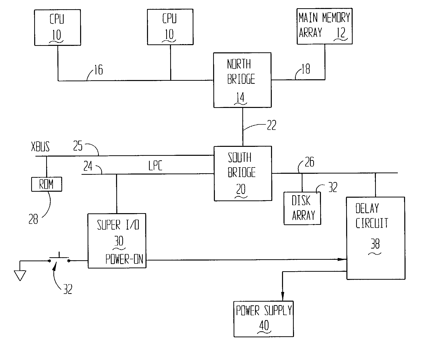
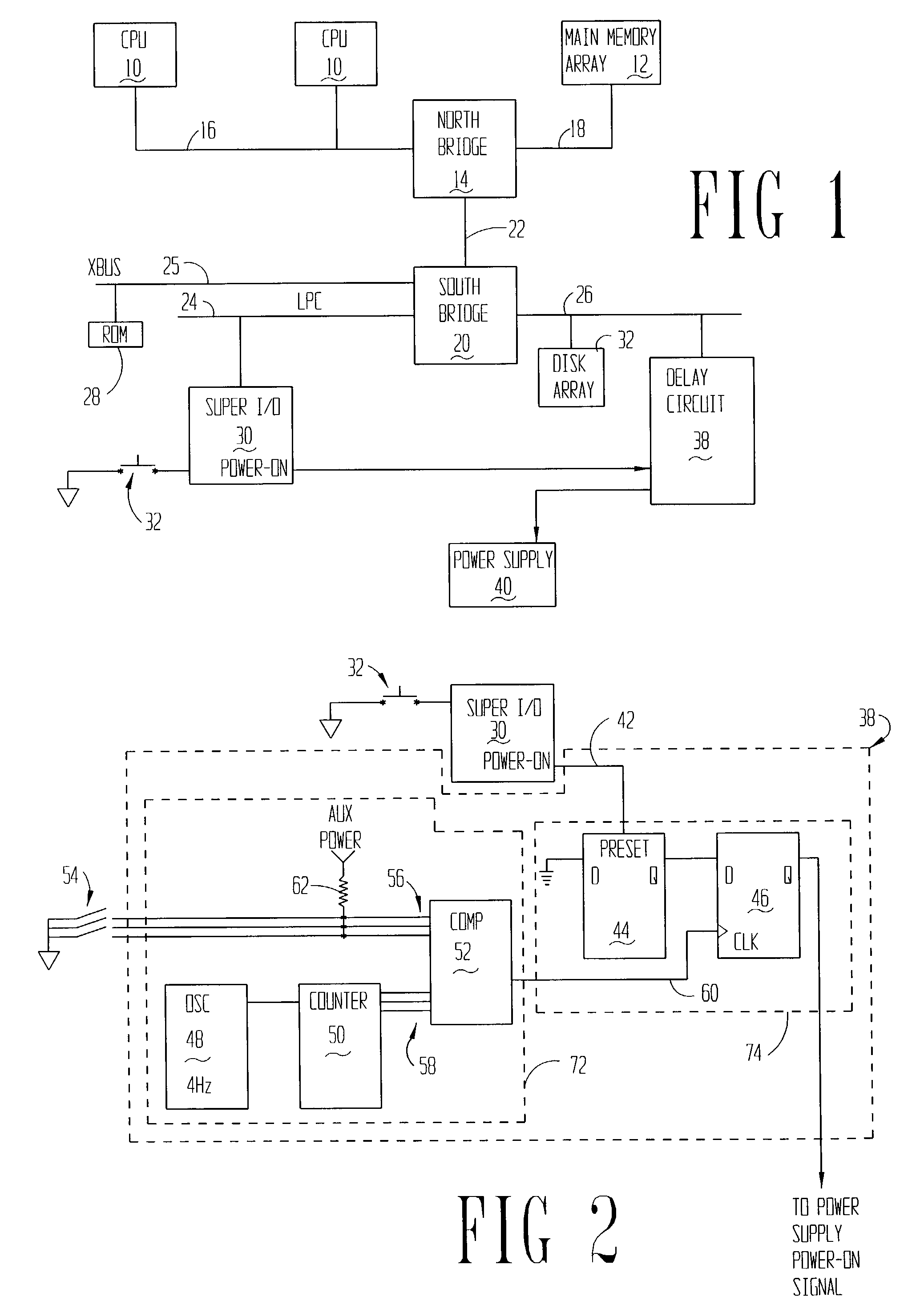
[0013]The problems noted above are solved in large part by a method and apparatus for staging or staggering the times that each server in a rack-mounted server system is allowed to power-on (if that was the server's previous operating condition) after a loss and return of power. The staging or staggering may take the form of setting each server to begin powering-on at a predetermined amount of time after return of power, and may also comprise a random or pseudo-random start time for each of the servers.

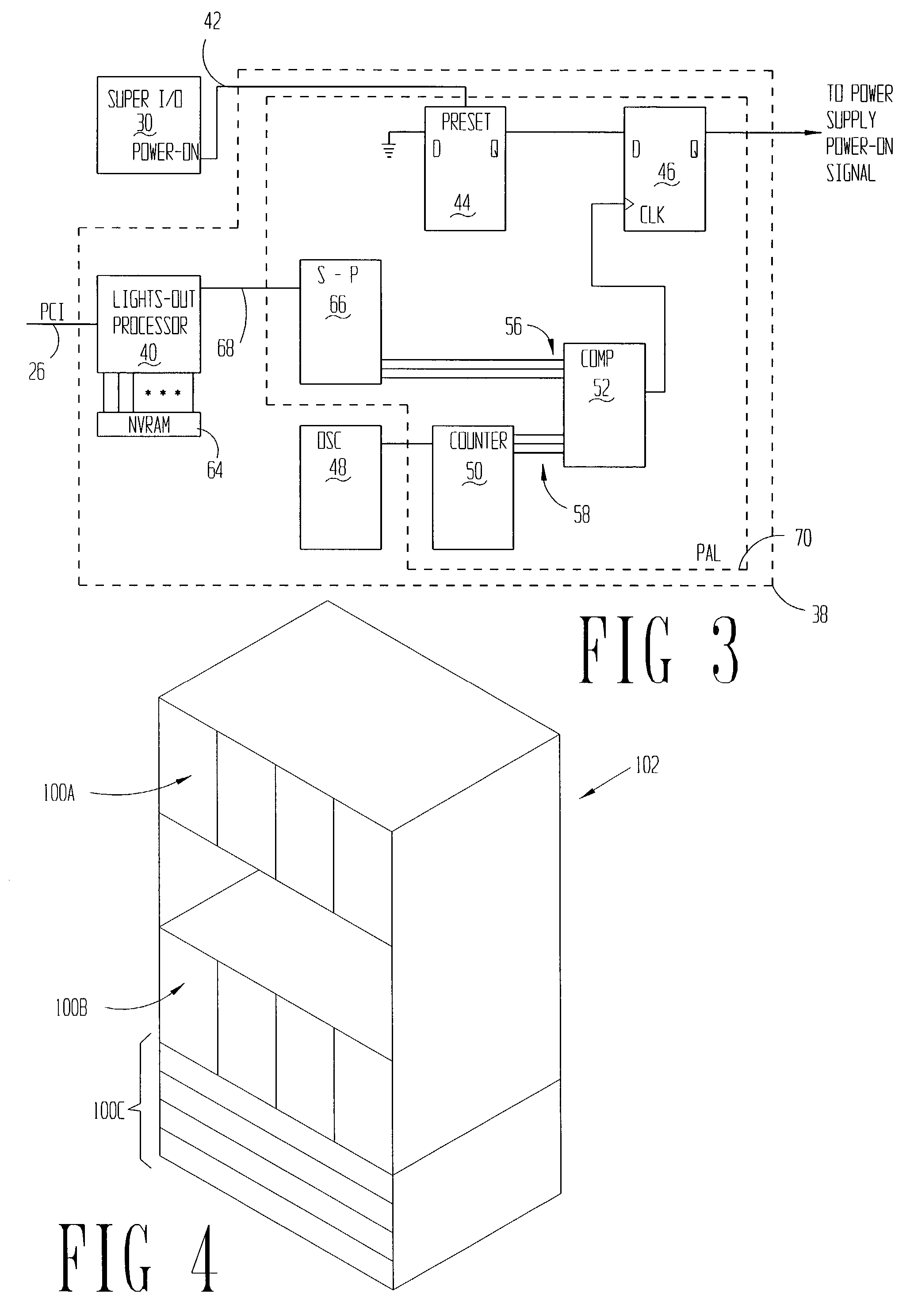
[0014]The preferred implementation comprises a programmable array logic (PAL) coupled in the circuit between the super input / output controller and the power-on input signal of the power supply. Based on the contents of a non-volatile storage in the computer system, preferably within non-volatile random access memory coupled to the lights-out processor, the PAL provides a programmable delay of the power-on signal propagating between the super input / output device and the power supply.

[0...


PUM


Abstract

The specification discloses a system and related method for delaying the powering-on of a server after loss of power. In this way, each server in a rack of servers may have its power restored at staggered times to minimize in-rush current associated with start-up of the rack-mounted server system.

Description

CROSS-REFERENCE TO RELATED APPLICATIONS[0001]None.STATEMENT REGARDING FEDERALLY SPONSORED RESEARCH OR DEVELOPMENT[0002]Not applicable.BACKGROUND OF THE INVENTION[0003]1. Field of the Invention[0004]The preferred embodiments of the present invention are directed generally to rack-mounted server systems. More particularly, the preferred embodiments are directed to reducing in-rush current when powering-on a rack or multiple racks of servers at the same time.[0005]2. Background of the Invention[0006]As the state of computer technology advances, the size of computers, especially servers, continues to decrease. While early server systems may have had multiple servers (or computers) in a single equipment rack, modern server footprints have decreased dramatically. In fact, it is now possible to put ten or more modem servers in the same physical space that one early server previously occupied. Further, modem servers typically contain multiple microprocessors, in spite of their smaller footp...

Claims


Application Information

Patent Timeline
Patent Type & Authority Patents(United States)
IPC IPC(8): G06F1/30
CPCG06F1/30Y10S323/908H02H9/001G06F1/329
Inventor FREEVOL, JASON W.EKROT, ALEXANDER C.
Owner HEWLETT-PACKARD ENTERPRISE DEV LP
Why Eureka
Try Eureka