Diesel engine system for use with emission control device

a technology for diesel engines and emission control devices, applied in the direction of machines/engines, exhaust treatment, mechanical equipment, etc., can solve the problems of increasing system costs, manufacturing complexity and wiring complexity, and increasing the cost of new technology, so as to reduce the amount of necessary reductants

Inactive Publication Date: 2005-11-29
FORD GLOBAL TECH LLC
View PDF27 Cites 18 Cited by
  • Summary
  • Abstract
  • Description
  • Claims
  • Application Information

AI Technical Summary

Benefits of technology

[0008]In this way, it is possible to minimize reductant needed to purge a NOx catalyst without the added cost and complexity of requiring multiple injectors. I.e., by this judicious plumbing, the present invention can achieve the same ability of directing lean exhaust flow of a large magnitude, and rich exhaust flow of a small magnitude with reduced system costs and complexity. In other words, the configuration according to the present invention can achieve the required functionality while eliminating a fuel injector and an exhaust control valve. Further complexity reduction and cost saving is achieved since there is similarly a reduction in wiring and plant manufacturing operations and complexity.
[0013]In this way, it is possible to minimize the amount of necessary reductant used from the first reductant injector. Further, preferably, only a single reductant injector is needed.

Problems solved by technology

The present inventors, however, have recognized a disadvantage with such an approach.
This additional hardware significantly increases system costs, as well as manufacturing complexity and wiring complexity.
The trucking industry is extremely cognizant of increased capital and operating costs of emissions related technology.
3B), additional cost of new technology is a major impediment to its implementation.

Method used


Image

  • Diesel engine system for use with emission control device
  • Diesel engine system for use with emission control device
  • Diesel engine system for use with emission control device

Examples


Embodiment Construction

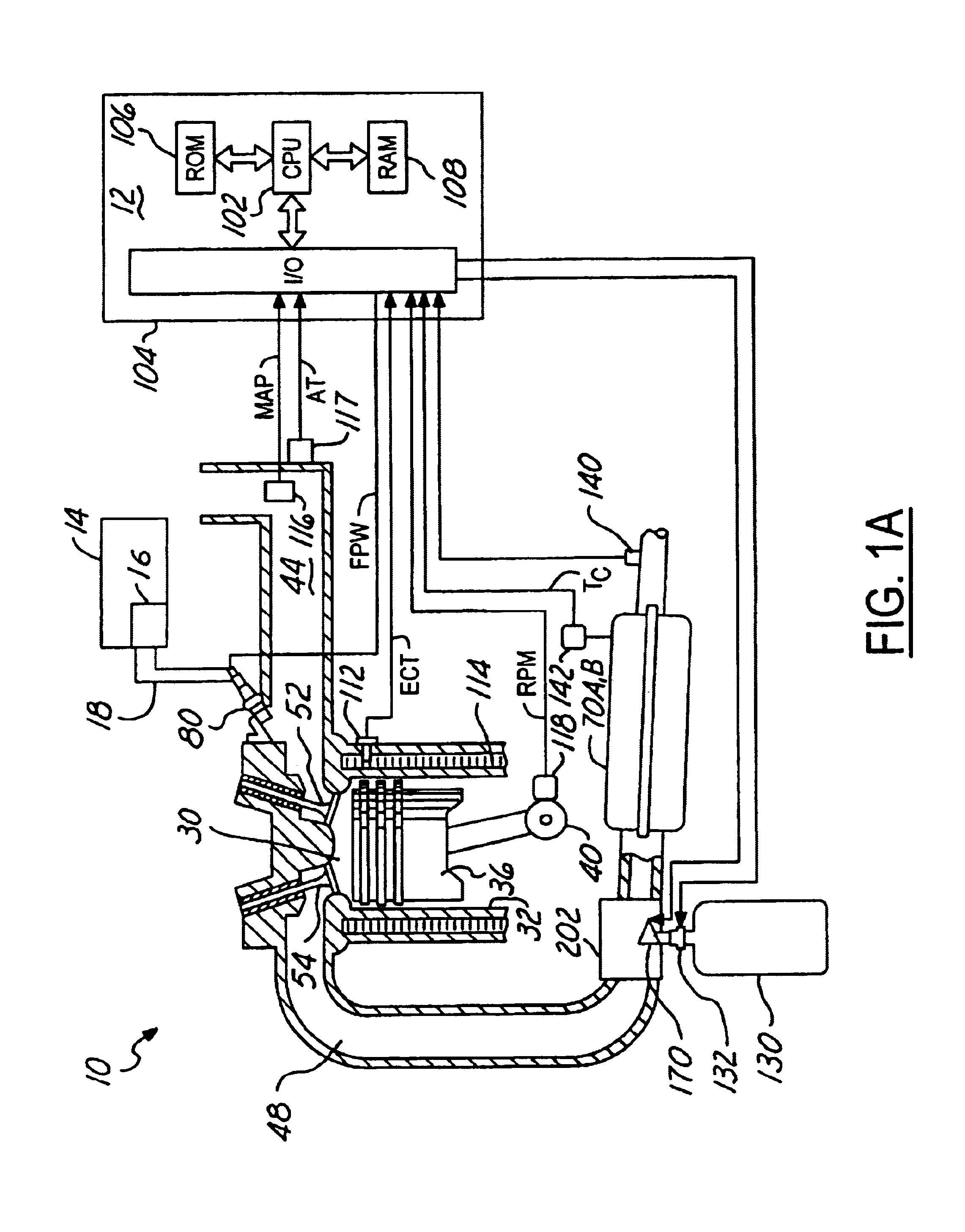
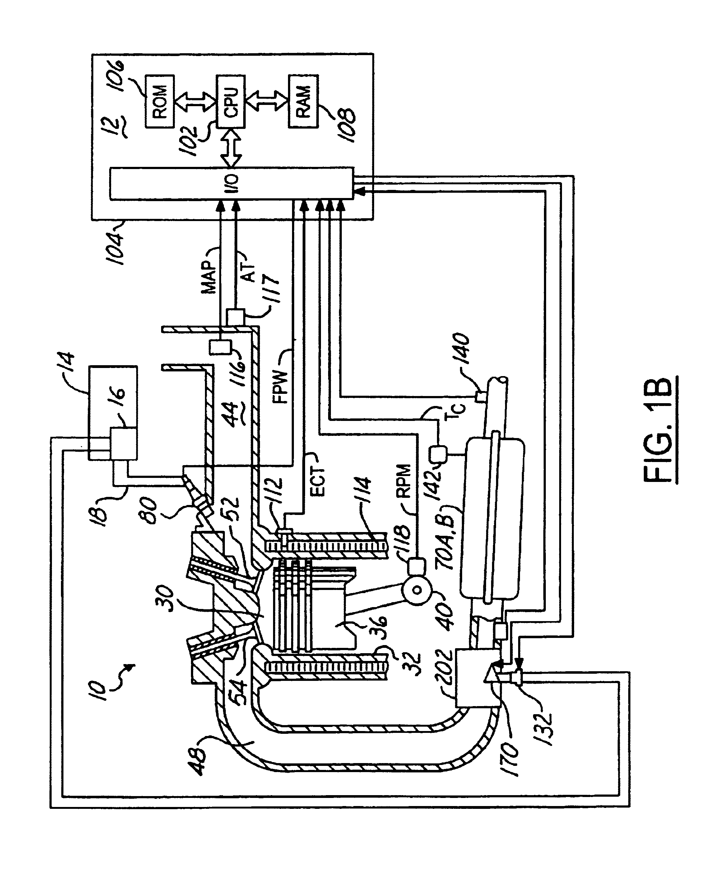
[0023]Internal combustion engine 10, comprising a plurality of cylinders, one cylinder of which is shown in FIG. 1A, is controlled by electronic engine controller 12. Engine 10 includes combustion chamber 30 and cylinder walls 32 with piston 36 positioned therein and connected to crankshaft 40. Combustion chamber 30 is shown communicating with intake manifold 44 and exhaust manifold 48 via respective intake valve 52 and exhaust valve 54. Intake manifold 44 is also shown having fuel injector 80 coupled thereto for delivering liquid fuel in proportion to the pulse width of signal FPW from controller 12. Both fuel quantity, controlled by signal FPW and injection timing are adjustable. Fuel is delivered to fuel injector 80 by a diesel fuel system including a fuel tank 14, fuel pump 16, and fuel rail 18. Alternatively, the engine may be configured such that the fuel is injected directly into the cylinder of the engine, which is known to those skilled in the art as a direct injection engi...


PUM


Abstract

An exhaust valve downstream of a diesel engine splits exhaust gasses between two catalysts. In one position, most of the exhaust gasses go to a first catalyst, and the remaining exhaust gasses, along with injected reductant go to a second catalyst. In a second position, most of the exhaust gasses go to the second catalyst, and the remaining exhaust gasses, along with injected reductant go to the first catalyst. In this way, a reduced cost system is achieved.

Description

CROSS-REFERENCE TO RELATED APPLICATIONS[0001]This application is a continuation application of and claims priority to U.S. patent application Ser. No. 10 / 064,626, filed Jul. 31, 2002, now U.S. Pat. No. 6,679,051, and is hereby incorporated in its entirety for all purposes.FIELD OF THE INVENTION[0002]Field of the present invention relates generally to NOx reduction of diesel engines having an emission control device that stores NOx during certain conditions and releases / reduces stored NOx during other operating conditions. More particularly, the field of the present invention relates to system configurations to reduce component part costs.BACKGROUND OF THE INVENTION[0003]Lean burn engines, such as diesel and gasoline engines, can provide increased fuel economy and power density. One approach to reduce NOx emissions uses a catalytic converter in the engine exhaust. One type of catalytic converter stores NOx when the engine is running lean, and releases / reduces the stored NOx when a ri...

Claims


Application Information

Patent Timeline
Patent Type & Authority Patents(United States)
IPC IPC(8): F01N13/08F01N3/08F01N3/20F01N3/24F01N3/28F01N3/36F01N13/04
CPCF01N3/0842F01N3/0878F01N3/0885F01N13/011F01N2610/02F01N2610/03
Inventor VAN NIEUWSTADT, MICHIEL J.UPADHYAY, DEVESHRUONA, WILLIAM CHARLES
Owner FORD GLOBAL TECH LLC
Why Eureka
Try Eureka