Dispenser for free-flowing products

Active Publication Date: 2005-11-29
RPC WIKO
View PDF11 Cites 5 Cited by
  • Summary
  • Abstract
  • Description
  • Claims
  • Application Information

AI Technical Summary

Benefits of technology

[0017]Through the simple design of the sealing element a simple manufacture with advantage is possible and also a simple installation of the sealing element in the application surface of the dispenser. Since the manufacture of the sealing element can be performed separately from the remaining structural elements of the dispenser, conventional elastic raw materials can be used, for example thermoplastic elastomers (TPE, also known as thermoplastic rubber or elastoplastics or thermoplastics), nitrile rubber (nitrile-butadiene rubber or NBR), nitirile silicone rubber, silicone or other rubber-like raw materials.
[0018]In accordance with a further design of the invention, the sealing element is not manufactured in one piece, but rather togeth

Problems solved by technology

However, with a dispenser of this type the danger exists that the loose plug sealing the discharge opening will be lost or accidentally thrown away by the user after a single use of the dispenser, so that dirt or bacteria can seep into the unsealed discharge channel and spread within the dispenser.
In addition, the possibility exists that a pl

Method used


Image

  • Dispenser for free-flowing products
  • Dispenser for free-flowing products
  • Dispenser for free-flowing products

Examples


Example

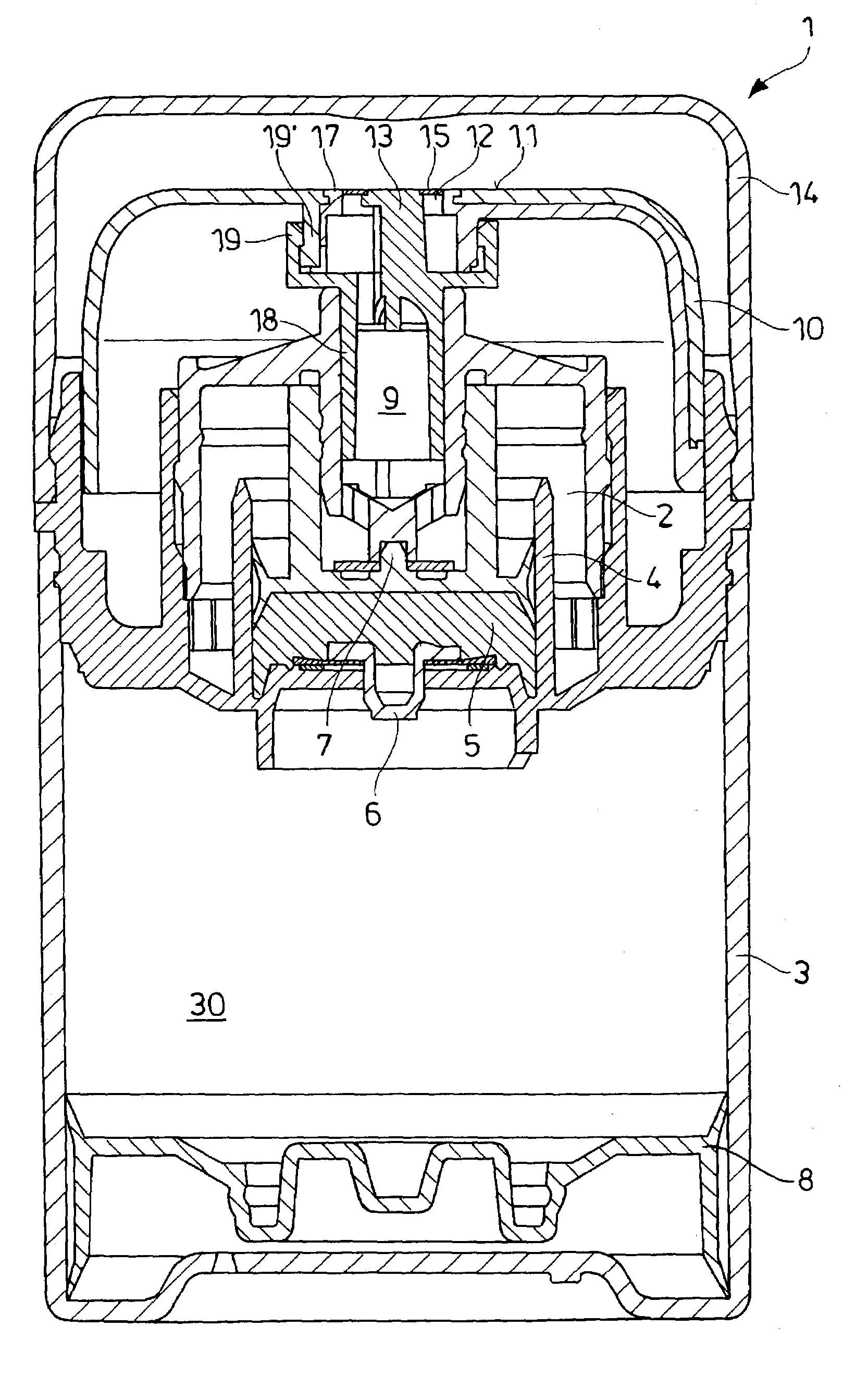
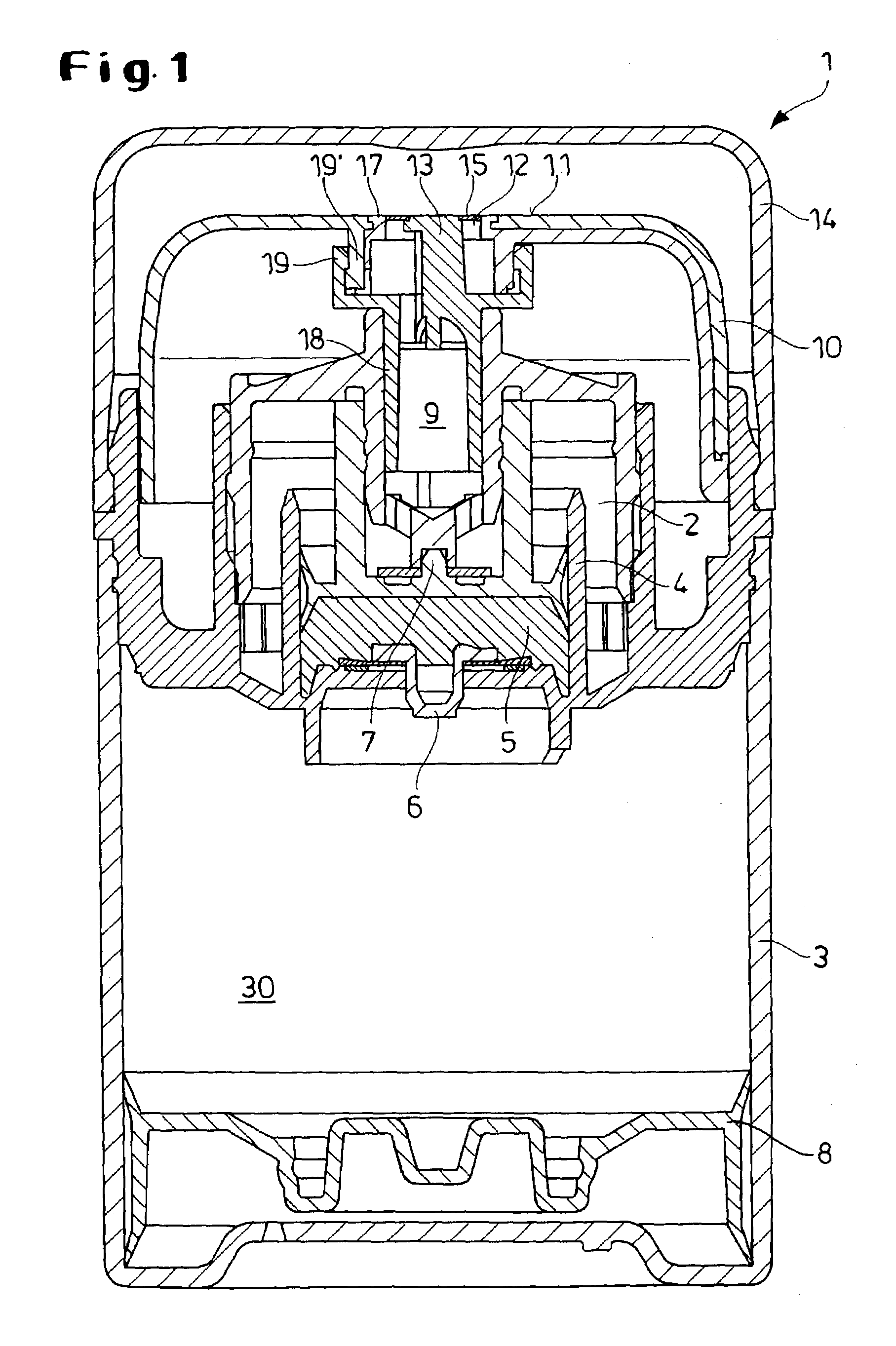
[0026]In FIG. 1 a dispenser 1 for distribution of measured quantities of fluid to pasty products 30 is shown in a vertical cross-sectional view with a developmental form of the application cap 10 in accordance with the invention. The dispenser 1 consists in its basic components of a storage container 3 for accepting the product 30 to be dispensed with a guide piston 8, a dispenser pump 4 with pump chamber 5 and a dispenser head 2 with a discharge channel 9 and a planar application surface 11 with an application opening 12. When not in use, the dispenser head 2 is covered with a locking cap 14.

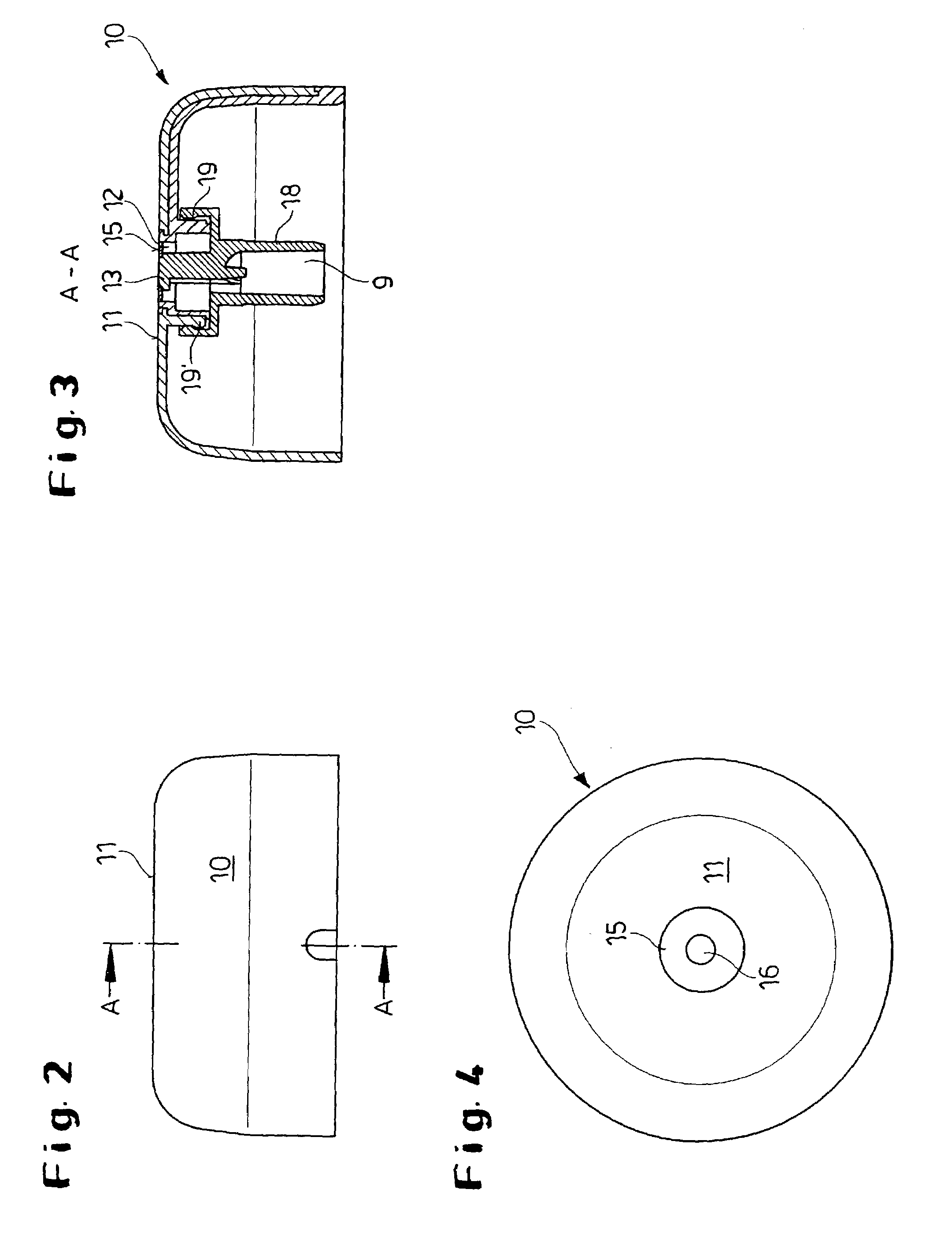
[0027]Within the dispenser head 2 a sealing pivot 18 is inserted from above, in which the discharge channel 9 is formed. This sealing pivot 18 has a spindle 13 centrally arranged, whose upper area seals flush or even with the application surface 11, and a rotary case 19 at a distance from the spindle 13.

[0028]A sealing element 15 is arranged in a recess 17 within the application surface 11 whic...


PUM


Abstract

A dispenser for distributing measured quantities of fluid to pasty product comprising a storage container with axially displaceable guide pistons and a dispenser head with a dispenser pump. A pump chamber is restricted by check valves at the entry and exit. A discharge channel is positioned downstream of the dispenser pump with an application opening that can be sealed by a sealing element. The dispenser head is designed with an application cap with a planar application surface closing the dispenser head in an axial direction and with an application opening centrally arranged in the application surface. The sealing element is designed in such a way, and arranged within the application surface, that the sealing element completely overlaps the application opening and is flush with the planar application surface.

Description

BACKGROUND OF THE INVENTION[0001]The invention relates to a dispenser for distribution of measured quantities of fluid to pasty products, comprising of a storage container with axially displaceable guide pistons and a dispenser head with dispenser pump arranged on the storage container, whose pump chamber is restricted by check valves at the entry and exit as well as a discharge channel inserted after the dispenser pump with an application opening that can be sealed by a sealing element.[0002]Various devices are known for the measured distribution of fluid to pasty products for squeezing out the product from the storage container through an application opening, which differ fundamentally with regard to the structural design and function.[0003]A dispenser of the foregoing described type is known from EP 0 048 420 B1. The dispenser consists of a hollow cylindrical storage container with a lower open end, which is sealed by an axially displaceable guide piston. The upper end of the sto...

Claims


Application Information

Patent Timeline
IPC IPC(8): B05B11/00
CPCB05B11/007B05B11/0072B05B11/0075B05B11/3001B05B11/0048B05B11/028B05B11/1001
Inventor HEUKAMP, WOLFGANG
Owner RPC WIKO
Why Eureka
Try Eureka